Universal Portable Keyboard (UPK)
Introduction
I acquired a Steam Deck in August of 2022. It's a great handheld computer, with many buttons. However, given the aggressive pricing, and gaming-focussed performance, why can't it by my 'laptop' too? It just needs some more buttons… So I made a keyboard, but the UPK doesn't stop there.
The UPK, which is primarily designed for the Steam Deck could (with some work) be adapted for use with basically any device. The design includes a stand for the Deck, and given that I want to use it as a proper computer, it also includes a USB-C hub. In theory, you could take your phone, tablet, or any other mobile, sufficiently-computery device, and adapt the system for it too. The grand idea would include custom-made stands for each device, with optional USB hub mounting options, that would all be compatible to the same keyboard. In essence, having one keyboard that can then be interchanged between any range of devices as desired. However, I don't quite have time for that so its just the UPK for the Steam Deck at the moment.
Once I started using my Deck, making a compatible stand was highest priority, so as it was made first, lets start with that:
Stand
Design Limitations
This design had a few requirements:
- The stand positions the Deck at a suitable angle for ergonomic desk-top use (pun intended).
- The hub can be mounted to the stand, and optionally removed if desired.
- The stand and hub can both fit within the back compartment of the Steam Deck case.
The last point constrains the design the most - the case's storage compartment has tapered walls and rounded corners, it requires the bottom of the stand fit (as a rectangle) within a 135mm x 50mm space, with a maximum size of 135mm x 60mm at the top of the taper, and a maximum height of around 22mm.
Firstly to physically sit with the keyboard, a flat front was most desirable. The back edge was designed to follow the taper to maximise the internal space and (unintentionally) positioned the ports of the USB-C hub more ergonomically for plugging cables in. Furthermore, the vertical restriction, imposed by the elastic strap that is attached to the back of the Deck's case, limits the height of the ledge that vertically supports the Steam Deck.
USB Hub
The next thing I needed to decide was which USB-C hub to get. For this, I wanted ports to only be on one side. With this, I'm referring to the longer sides of they typically rectangular hubs. This is because if they are on both 'long sides' the keyboard, which is to sit in front of the stand, would physically block half the ports. This is obviously less-than ideal. In addition, it would have to go entirely under the Deck and would increase the height of the design. This would limit the support for the deck and likely cause stability issues. I was also looking for USB-C hubs that aren't too expensive, as I found some that would have been suitable but were >£60. In the end, I settled with the "UGREEN Revodok USB C Hub, 7 in 1 USB C Adapter" for £24 (now often seen at £17.99), because of its long slim design, short cable and ports only on one of the 'main sides'. It also includes all the I/O that I wanted and more, which is great.
Stand Design
Using Valve's 3D model of the Steam Deck, and my custom-made model of the USB-hub, I was able to accurately model the dimensions of the components. Then using Fusion 360's 'Combine' function, I was able to take the intersection of the bodies. This required a lot of testing to get the correct tolerances and offsets for the fitment to be tight enough to hold, but not too tight as to inhibit removal of the Deck or hub.
As the USB-C hub has an SD and micro-SD card port on the left side, cut-outs has to be made - same
for the cable on the
right side. The two 'nubbins' for the Deck align with the bottom two screw holes of the case to slot
it into place. These
were inspired by loicloic's
designs.
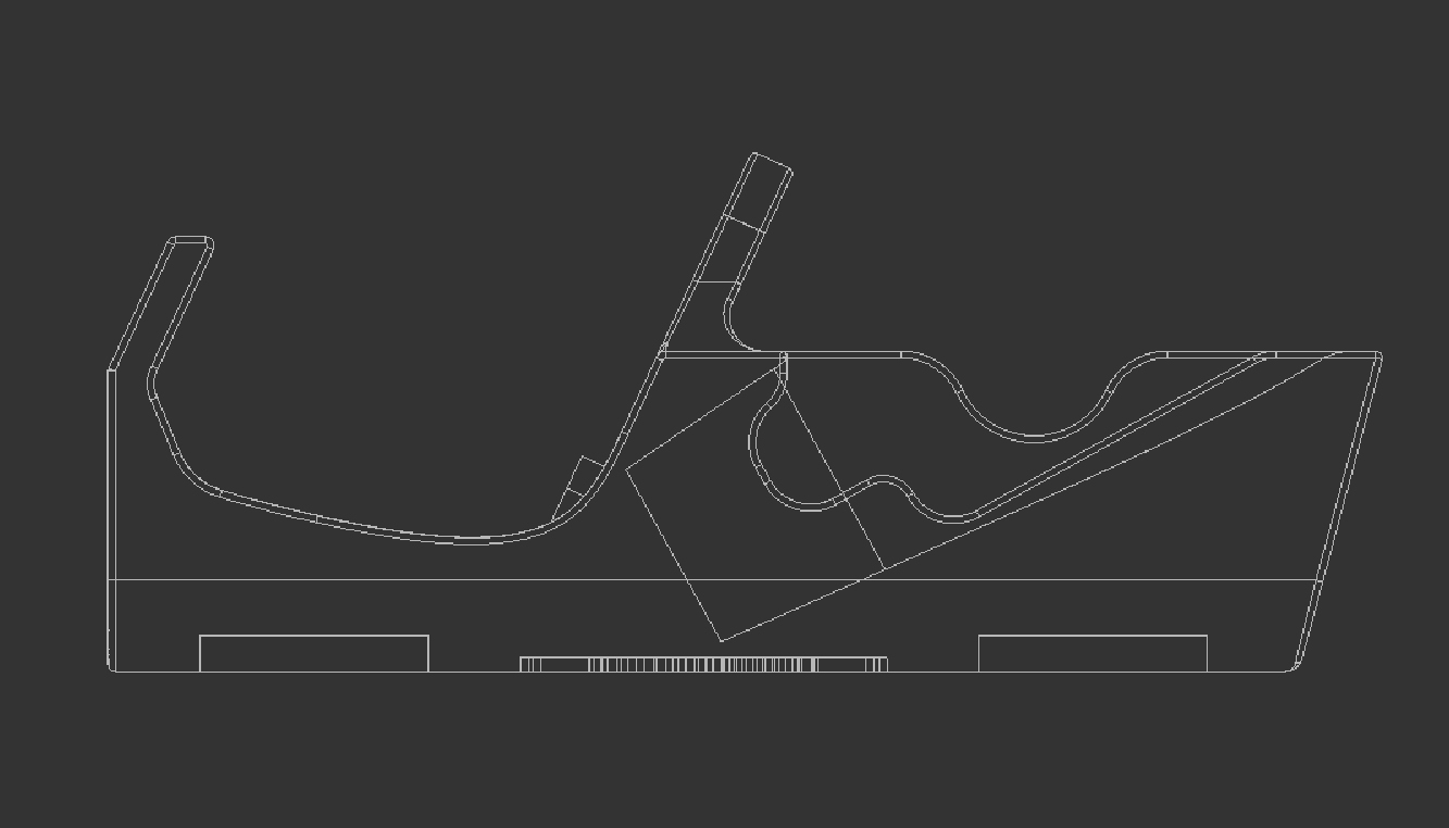
As shown by the side profile, there is not large amounts of space surrounding the dock - with close
proximity to the
logo underneath and the Deck itself. In some previous revision, I found that the underneath
was too thin and light
could shine through. Space for rubber feet was also provided.
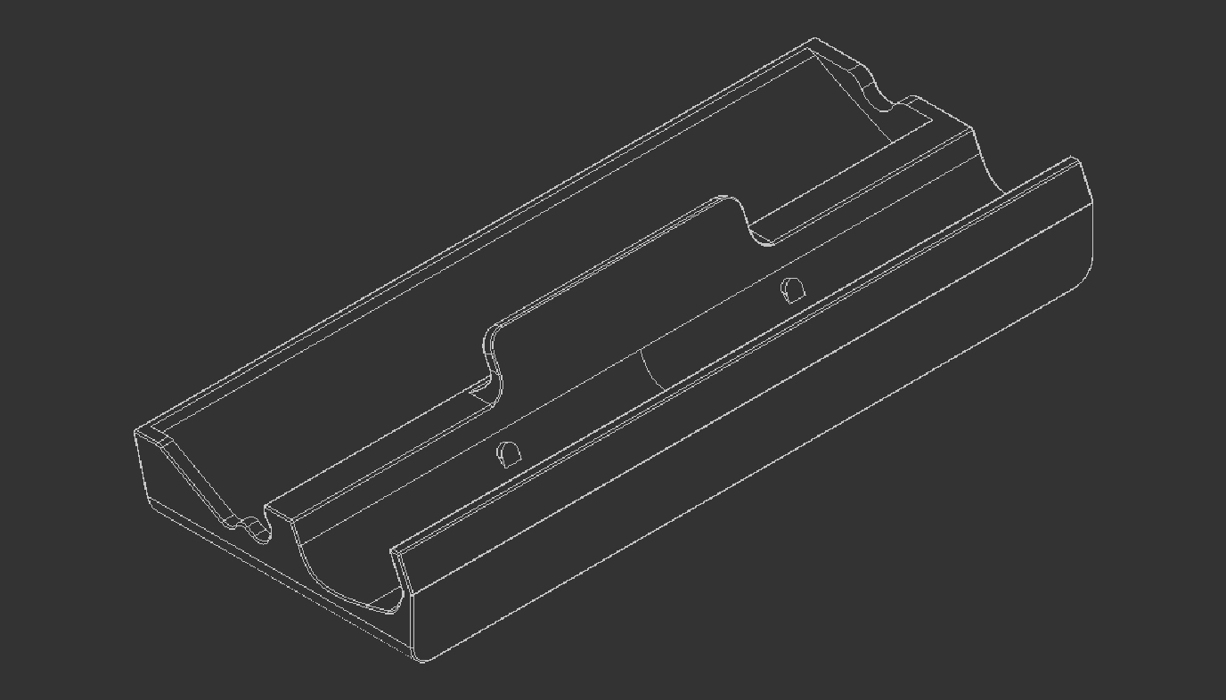
I had the intention of using magnets to dock the keyboard to the stand, so there are sufficient mounting points in the case. However, I am yet to integrate this into the stand due to the space requirements set out. It will take some more tweaking of the layout of the stand, before enough space can be allocated to the flat front of the stand, and given the proximity, I have concerns of the magnets interfering negatively with the Deck.
Keyboard
Components & Design
If I want to make a keyboard that is portable, it wants to small, or as small as it can be in any given dimension. Obviously there is a limit to this before too much functionality is lost or the performance of the system is degraded.
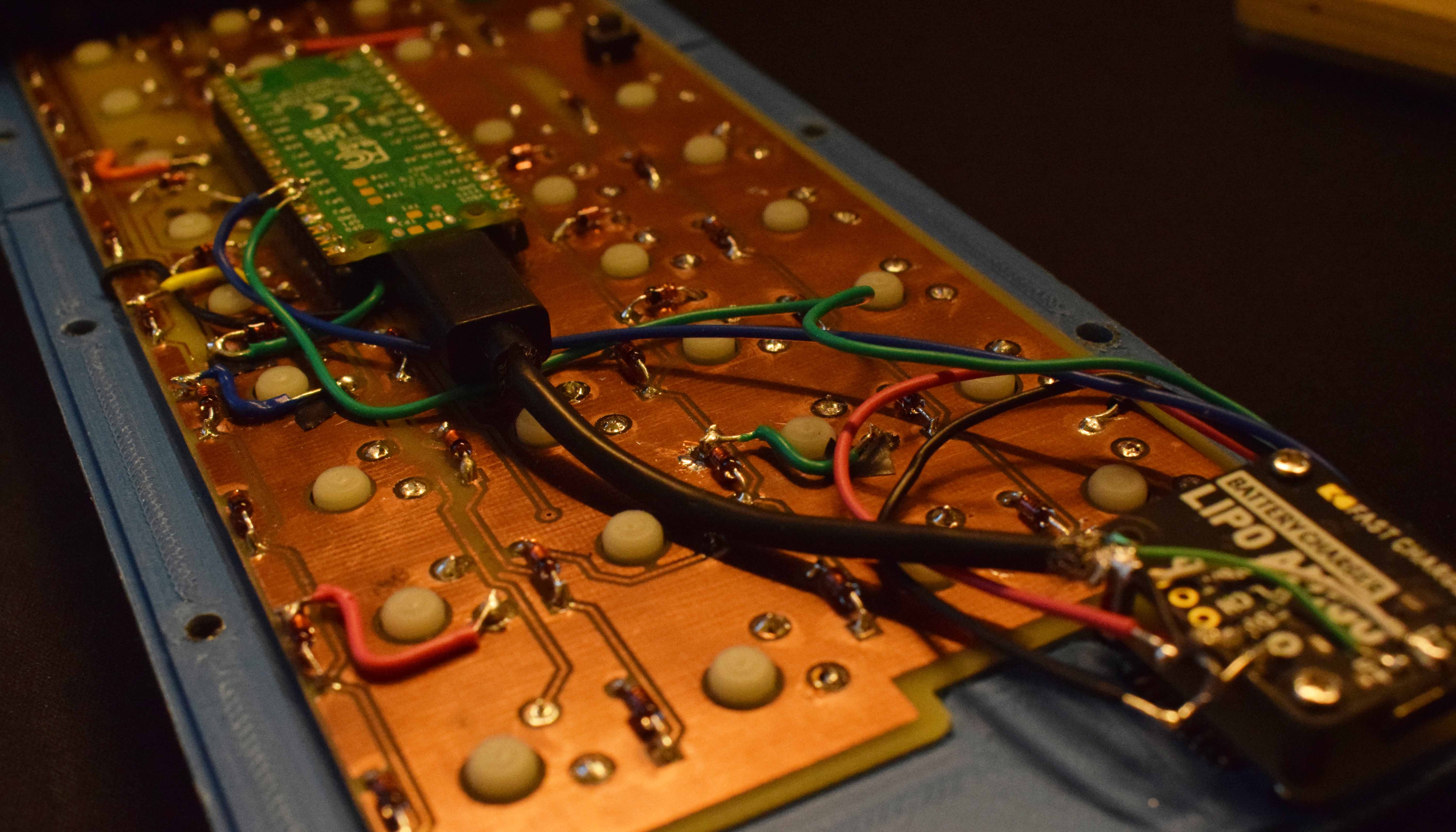
The microcontroller of choice was the Raspberry Pi Pico W, basically because of its W(ireless) capabilities at such a low price. It is less commonly used for custom keyboards as it uses an RP2040 processor as opposed to an Atmega32U4 chip that is found on the likes of the Pro Micro. Unlike the latter, the former does not have support for QMK, so its Circuit Python equivalent - KMK - will be used instead. At the time of writing, however, Bluetooth for this board is yet to be implemented, which is unfortunate. The idea remains to make this a wired and wireless capable board, through the inclusion of a LiPo battery and Pimoroni LiPo Amigo battery charger board. For the moment, the Amigo's USB-C port has been directly wired to the Pico, and is just wired. There is also a hole for a power switch, but that remains unused.
Given the portability requirements, I tried to make it as thin as possible. Realistically, the Pico was to be mounted below the switches, which limits the minimum internal height. To shave a few millimetres above the plate, I chose Low-Profile Gateron switches. For the Amigo to fit, it has to go next to the key matrix, which intern limits the minimum length.
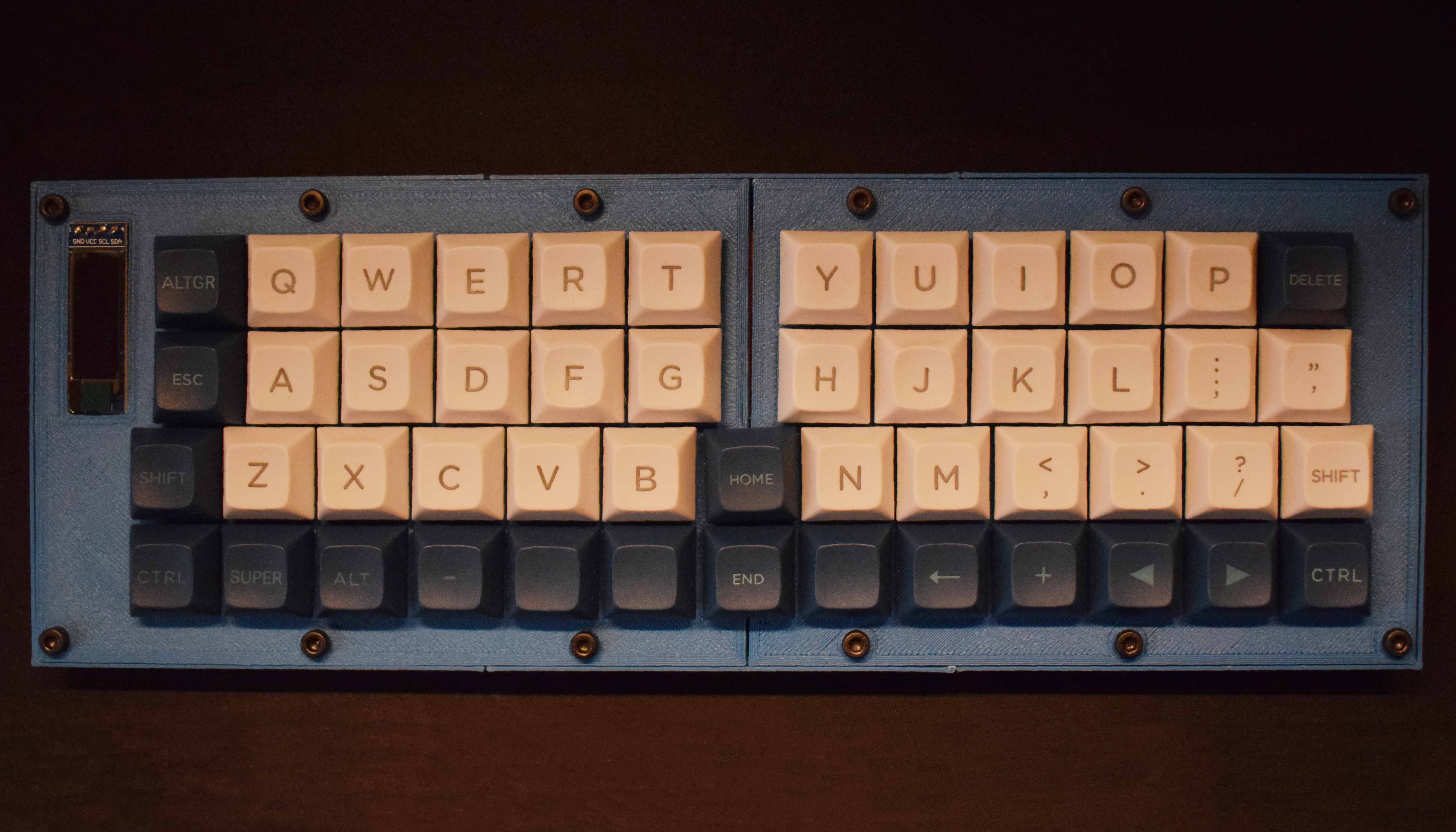
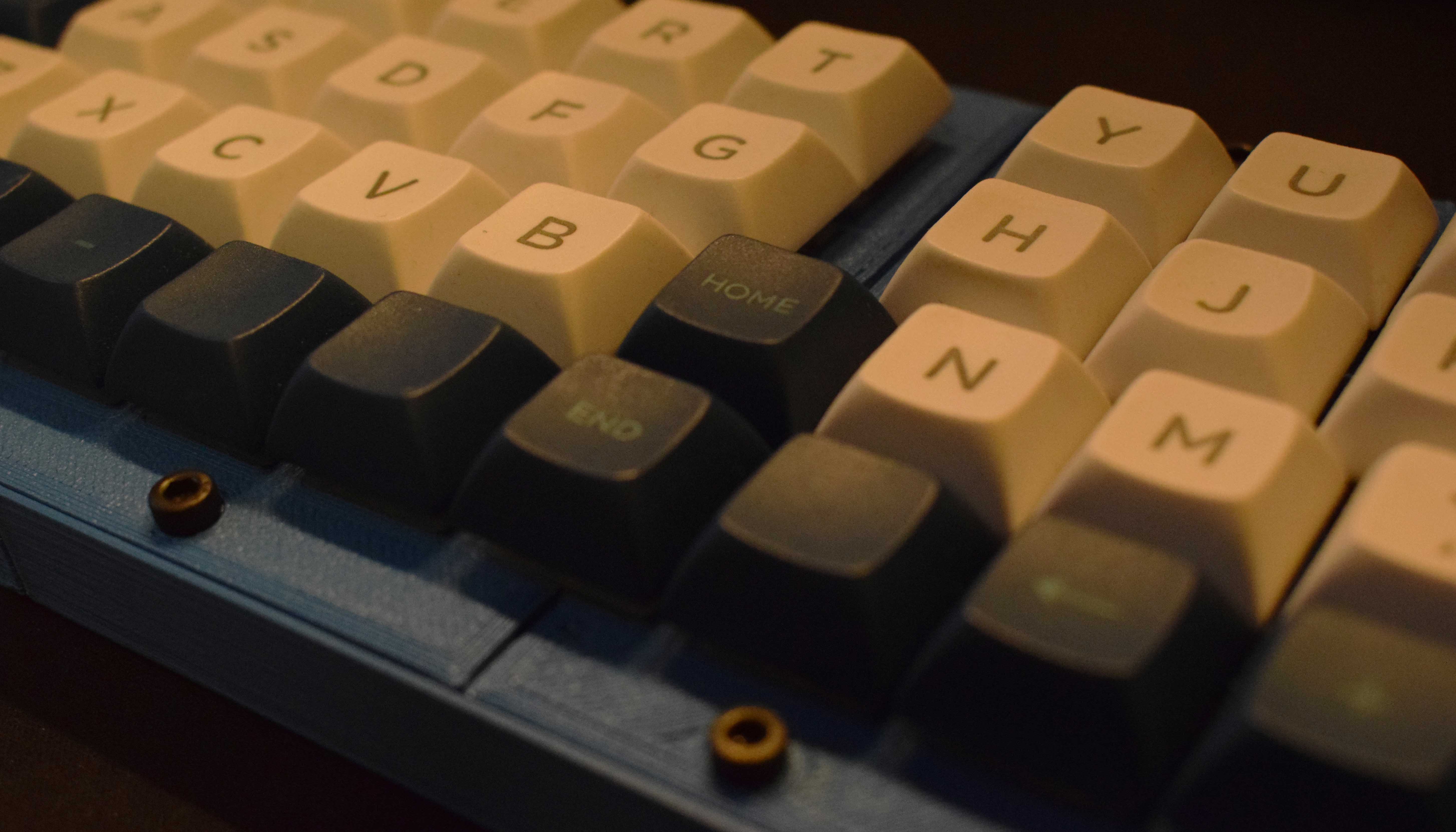
As I already use an 'unconventional' keyboard, I can take some liberties in the key layout. The physical number and F-row, the navigation cluster and numpad were removed as they can be implemented through layer keys. This makes it a 4-row keyboard and an (approximately) 40% layout - it has 50 keys in total. Ergonomically, I dislike the 'Planck' or similar layouts, as your hands end up too close together and you adduct your wrists. To counter this, the rows are counter-staggered to allow both hands to approach the keyboard at an angle. Furthermore, the addition of the 'home' and 'end' keys, whilst also being very useful, provide a slight distance between the hands such that they do not interfere with each other.
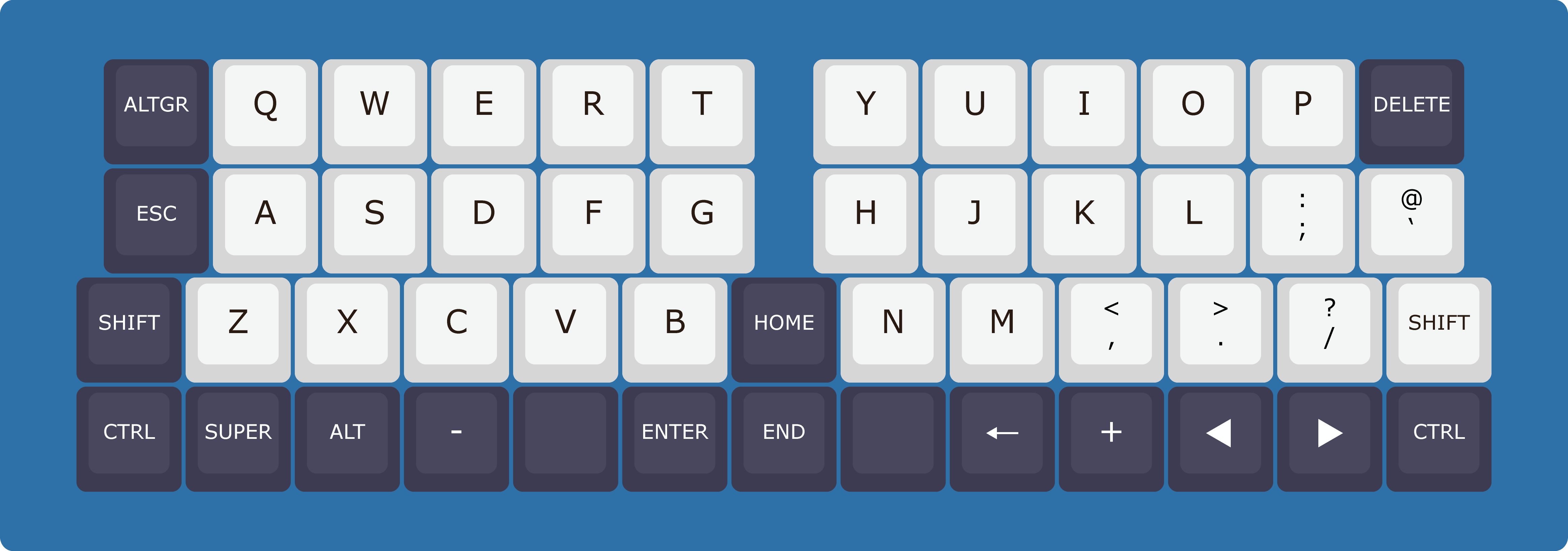
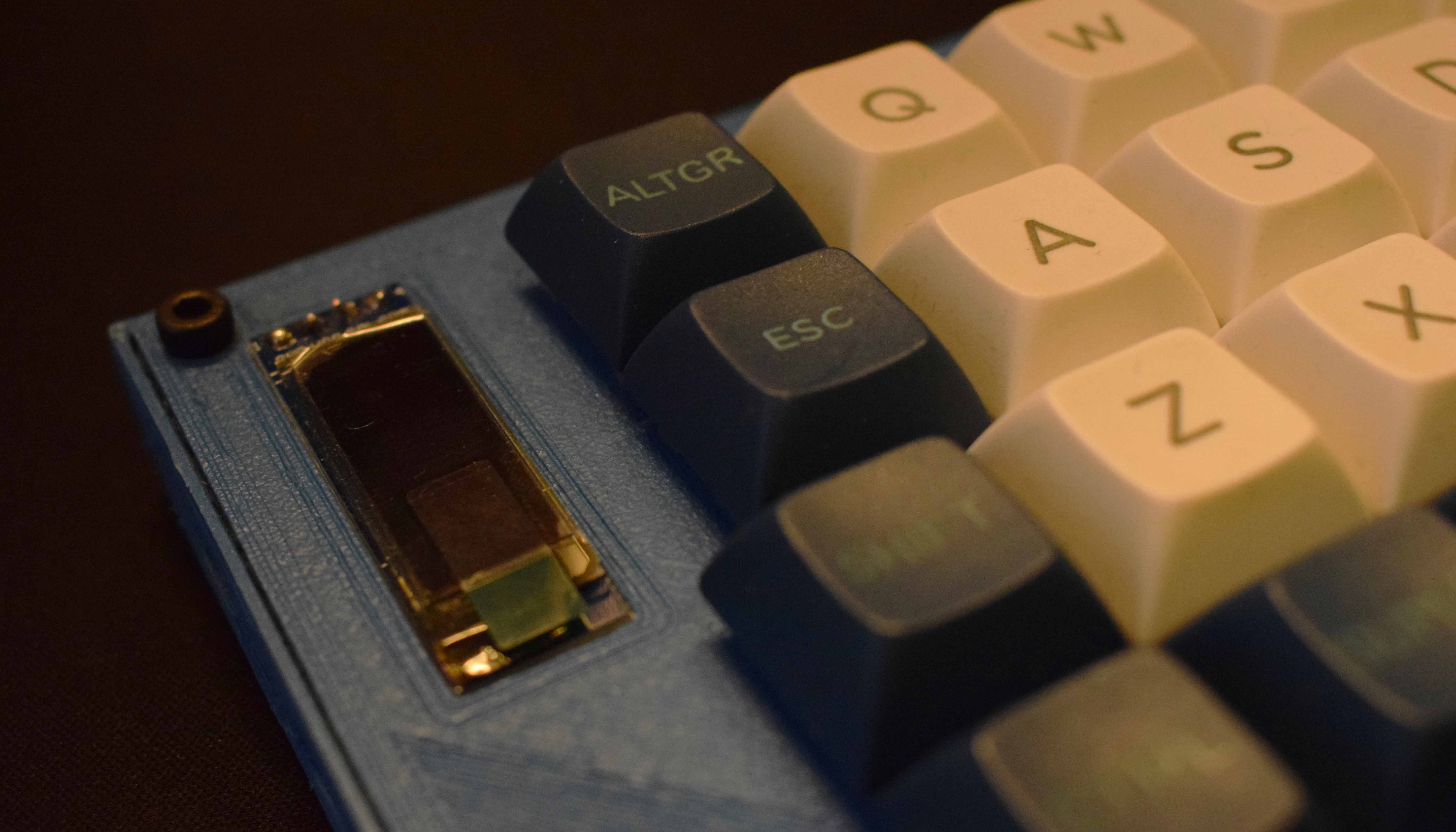
The OLED screen was a last minute addition that was easy to implement into the physical design as there was already space on the left side.
To PCB or not to PCB
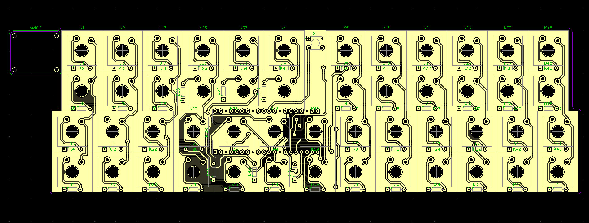
Originally, I was going to hand-wire the board, and skip the PCB because it would cost more and require more time. However, I was persuaded by the PCB prototyping lab that I recently acquired access to, to get one made there. This meant I had to learn how to design a PCB because this was first time I was doing it. This meant that not everything went as planned and there were plenty of mistakes. To begin with, when making the design, it took me a decent amount of time to realise that the pin layout of the Low-Profile Gateron switches is not the same as a standard Cherry switch. Instead it has a wider central stem and the two pins are in completely different places. Therefore I had to make my own pattern too. Once I got the first board printed, I also realised that I did the pattern backwards, and it needed flipping horizontally. The list could go on, but in the end, I made two boards and they worked fine.
3D Printed Case Design
My previous custom keyboard had a case made from layers of laser cut plywood and acrylic, but I no longer have access to that laser cutter, and I used up all of the 1.5mm plywood that I purchased. So instead, I spent hours in CAD software making a 3D printable case. The difficulty of this is the limitation of the print-bed dimensions. My printer can do 220mm x 220mm, but that isn't sufficient for the length a keyboard, even given the compact design that I produced. This made the construction more interesting. The general design is similar to my previous keyboard project - with the switches mounted through the top plate, and then the 'body' to fit around - but that's where the similarities end.
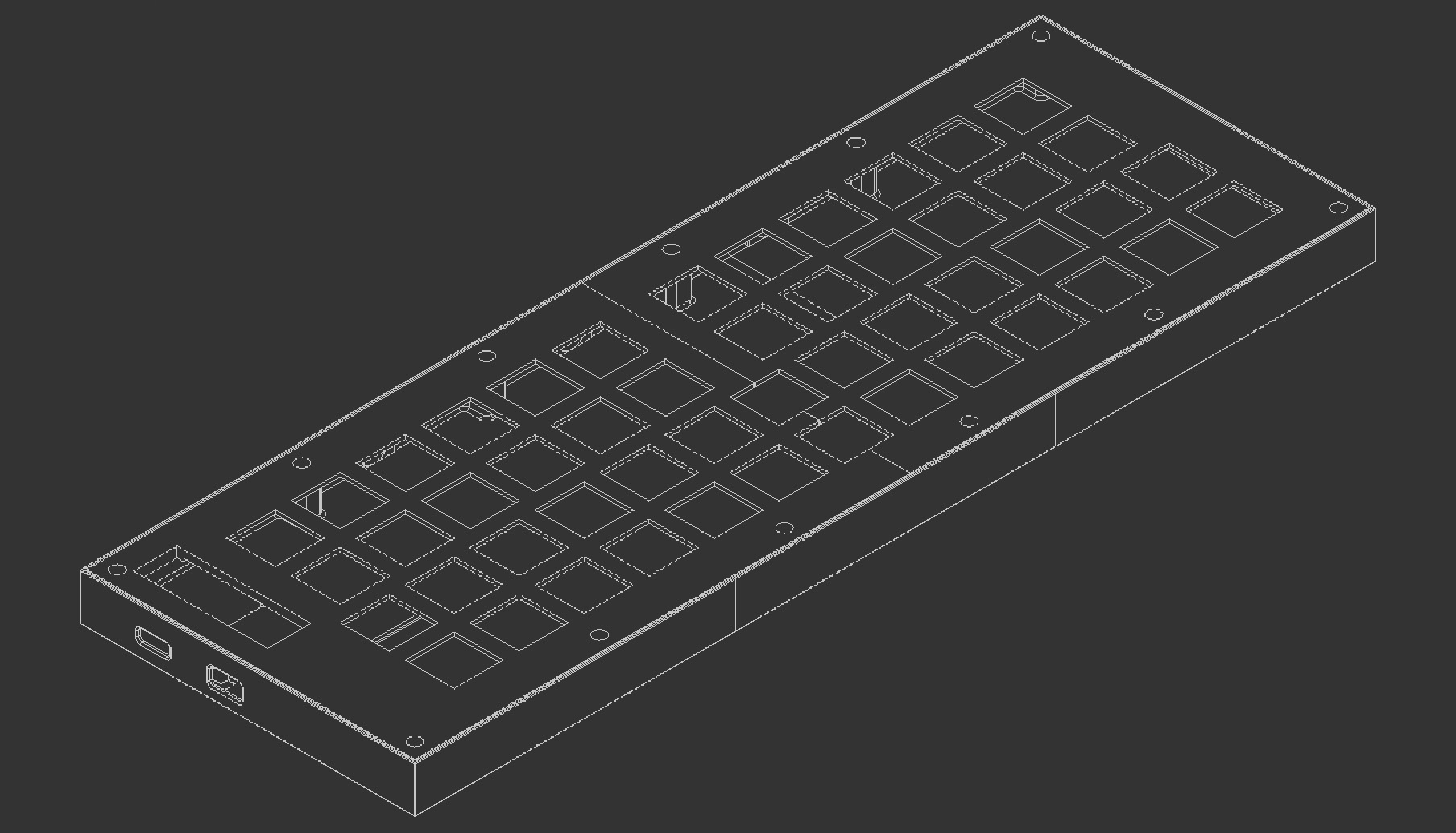
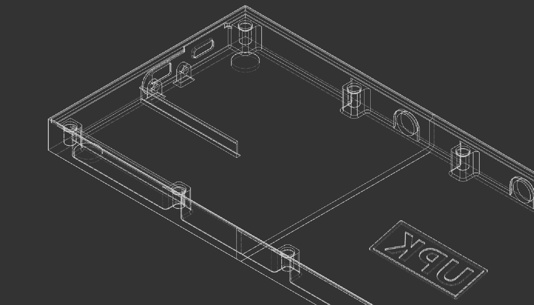
To fit this on the print bed, the top plate was split in half, and to
maintain some structure to the case the 'body' was split into three.
This can be seen below:

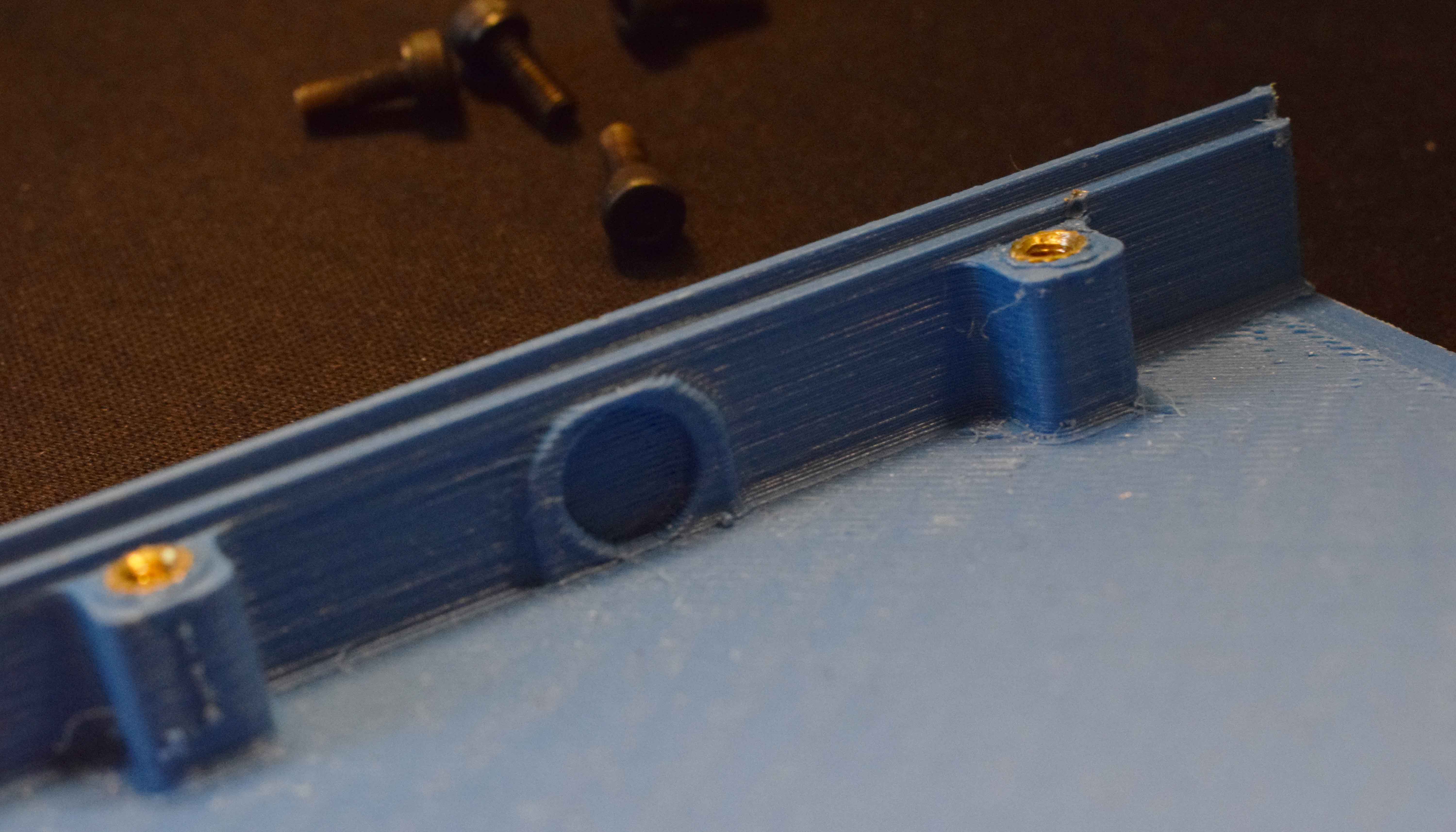
The switches mount through the top plate into the PCB. The PCB holds the Amigo and connects the Pico to all necessary components. Additionally, the OLED rests on top of the PCB and is friction-fit in to its slot. The design requires 12 screws to adjoin all five parts together, and through the use of threaded inserts, assembly is fairly simple, albeit tedious. As this is the first time I've designed something quite like this, not all tolerances for fitment with the screw holes was quite perfect, but that was sorted with the assistance of some needle files. The plate slots into the body and is held together by a collection of M3 bolts. When wireless capability is working, the battery is to go in a tray area with some double-sided tape or equivalent. Finally, for good measure, a fabric case was sewn for protection whilst in transport. Especially when printed in PETG, this is a surprisingly sturdy case which should hopefully be quite durable.
Given that I was not originally intending to have a PCB, I finished a design that would have worked without one, then had to remake the whole thing again to accommodate for the different requirements. I did attempt to make a parametric case design, but it became to complicated and began to fall apart.
Conclusion
Whilst the lack of wireless functionality is marginally disappointing, it does not prevent it from working overall. Personally, I find the system meets all other criteria, and is great to use with the Steam Deck. Its smaller in every dimension compared to my previous custom keyboard. Some more tweaking will still, of course, be required. I need to get some sort of foam to dampen the sound of the switches, as they are too loud in an academic environment. Its reasonably sturdy in PLA, with only some flexibility in the upwards direction, so I may have to look into some solutions for that. At the time of writing, I've been using it for about a week and I'm already fine with the even-more stripped down layout, and whilst no number-row is mildly inconvenient, the layers make it a non-issue. I will admit that it is slightly heavier than I expected it to be, but it does require a fair few hours to print. KMK also has a few oddities as it requires the Pico to be detected as a removable drive before it can be used, but I will have to look into all the firmware some more.
It was another long project, but I think I've achieved my goals, and its always funny to get comments about using a Steam Deck with "whatever the heck that is" as a laptop.
