Custom DIY Type-C Microphone
Introduction
For many years, I have used whichever microphone was most convenient - typically the one that connected to or was integrated with headphones. However, these are notoriously not-great-sounding and aren't designed for more than communication with friends or colleagues.
So after watching DIY Perks' Video on building a USB-C microphone, I took inspiration to make my own. This video was originally advertised as 'building a £30 microphone' - of which, that was the cost of only the capsule. The part that didn't cost £30 was the brass, but I will come back to this later.
I've stated where this project was sparked from, but this doesn't mean I've merely replicated the design. To begin with, I redesigned the electronics to not require buying and dissecting a USB audio interface adapter. This 'box at the end of the arm' (referred to as 'electronics box' from now on) was redesigned for the different requirements as analogue signals are output instead of digital ones. I added mute functionality and an indicator LED to go with it. Furthermore, to make it easier to make, part of the design was simplified.
With that out of the way, lets start with the design of its metaphorical brains…
Internal Electronics
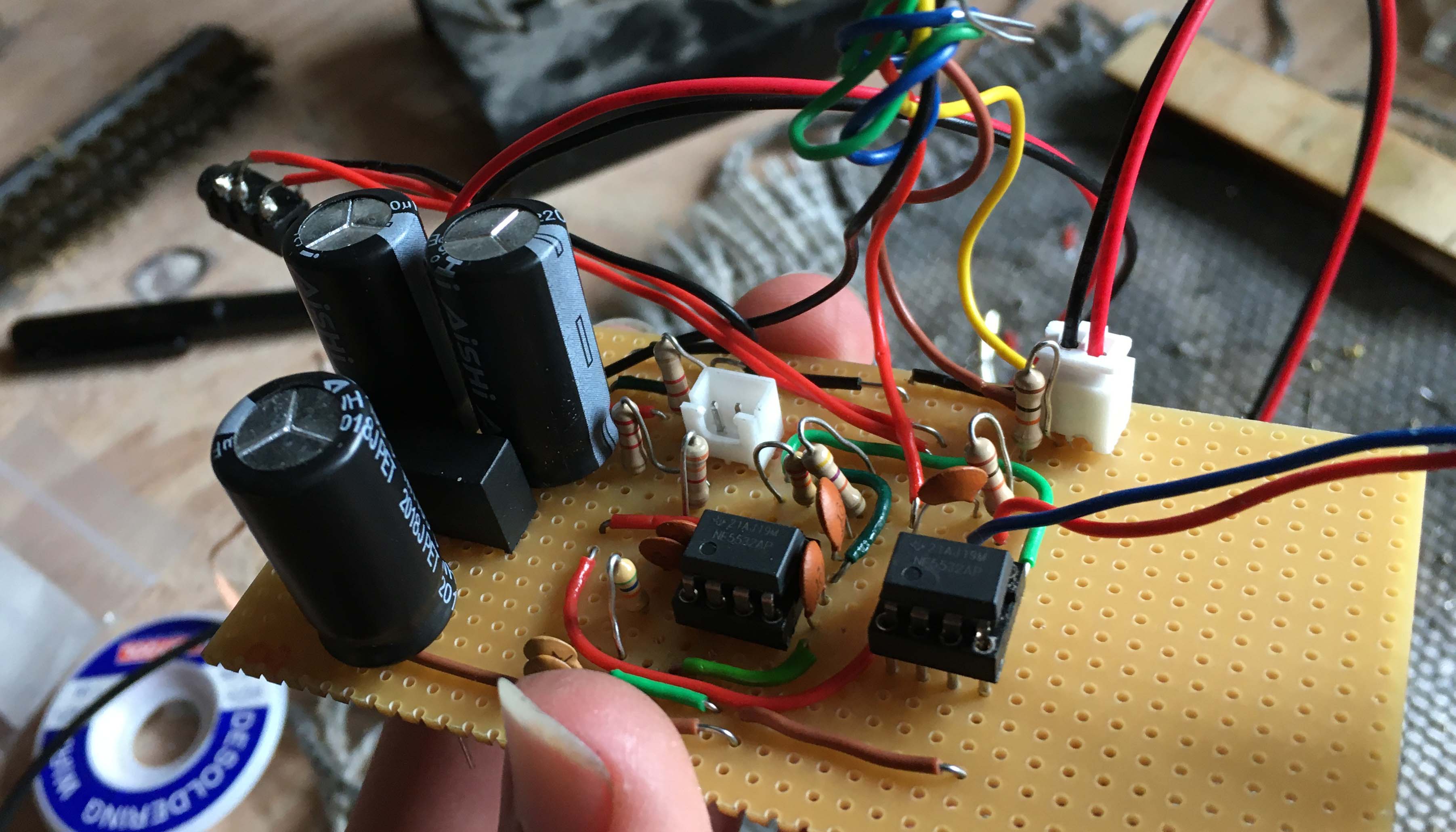
Keeping with the already-proposed microphone capsule - the JLI-2555BXZ3-GP - and a 2N4416 FET paired with it, I had some experimentation to do. The first job was to get it to work. I attempted different circuits on breadboard to varying degrees of success (partially the breadboard, partially the high background noise in the room I worked in) and tried to find what worked best from the knowledge and components I had accessible. The final design mainly consists of a 2-stage Butterworth bandpass filter followed by a non-inverting amplifier. This filtered out unwanted frequencies and produced a line-level output (with smoothing, decoupling and such added as well). For power, a Type-C port provides +5V, which is boosted to ±12V by a Murata DC-DC converter (CMR0512S3C). Then the output is taken by a 3.5mm TRRS jack as an analogue signal intended for a desktop input. So it's technically a 'Custom DIY Type-C and TRRS Microphone' but for my uses, this is acceptable - and it can always be changed later if desired.
Once the circuit design was confirmed, it was soldered to a piece of IC stripboard, and I could move on to the brass.
Brass, More like Pain in My ***
*cough*, sorry did I just write that? oh well, it's staying now…
I'll start by saying that I have never worked with brass before, and I don't have access to a proper workshop with the proper tools. So what did I have?
- A junior and senior hacksaw (the latter needed new blades)
- A drill stand (bought for this project)
- A blowtorch (also bought for this project)
- The most generic soldering iron possible (which needed new replacement tips)
So there were some investments made, but at least all the items were put to good use (and used for other projects too). The other critical tool was a 3D printer to make small jigs/guides such that holes could be drilled, and pieces could be cut with far more precision.
The workshop has gone from underequipped to marginally-more equipped and the precision of making has gone from none to just about sufficient. PROGRESS!
Capsule Holder
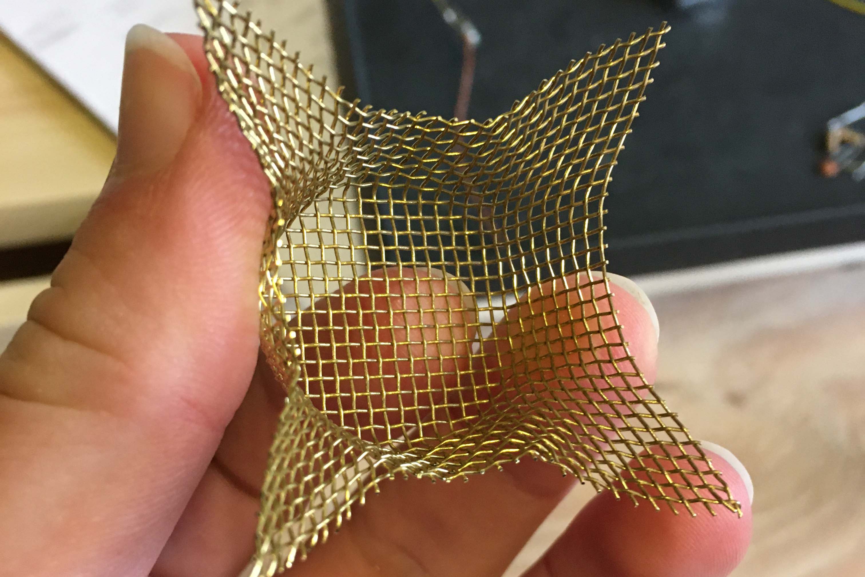
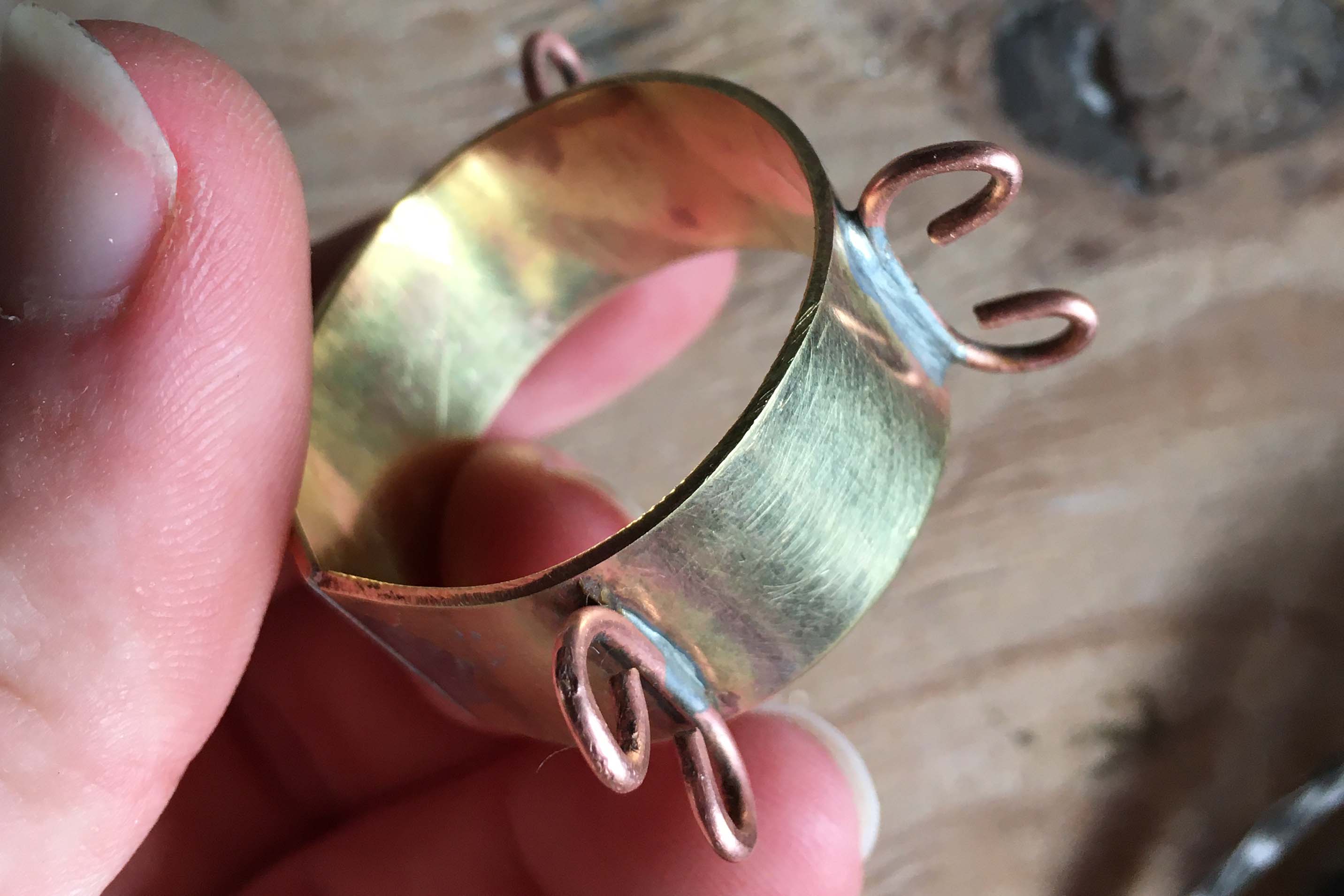
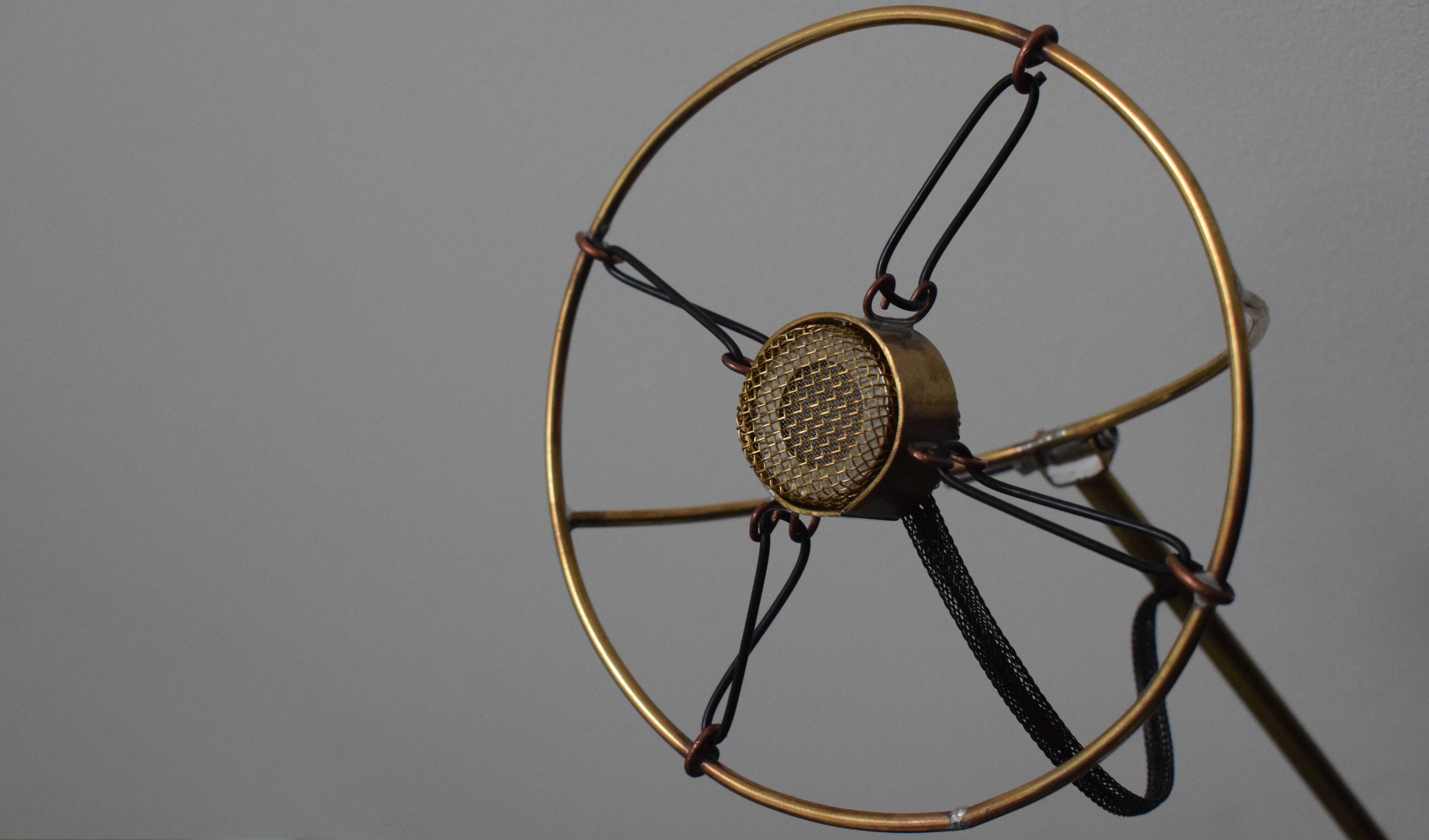
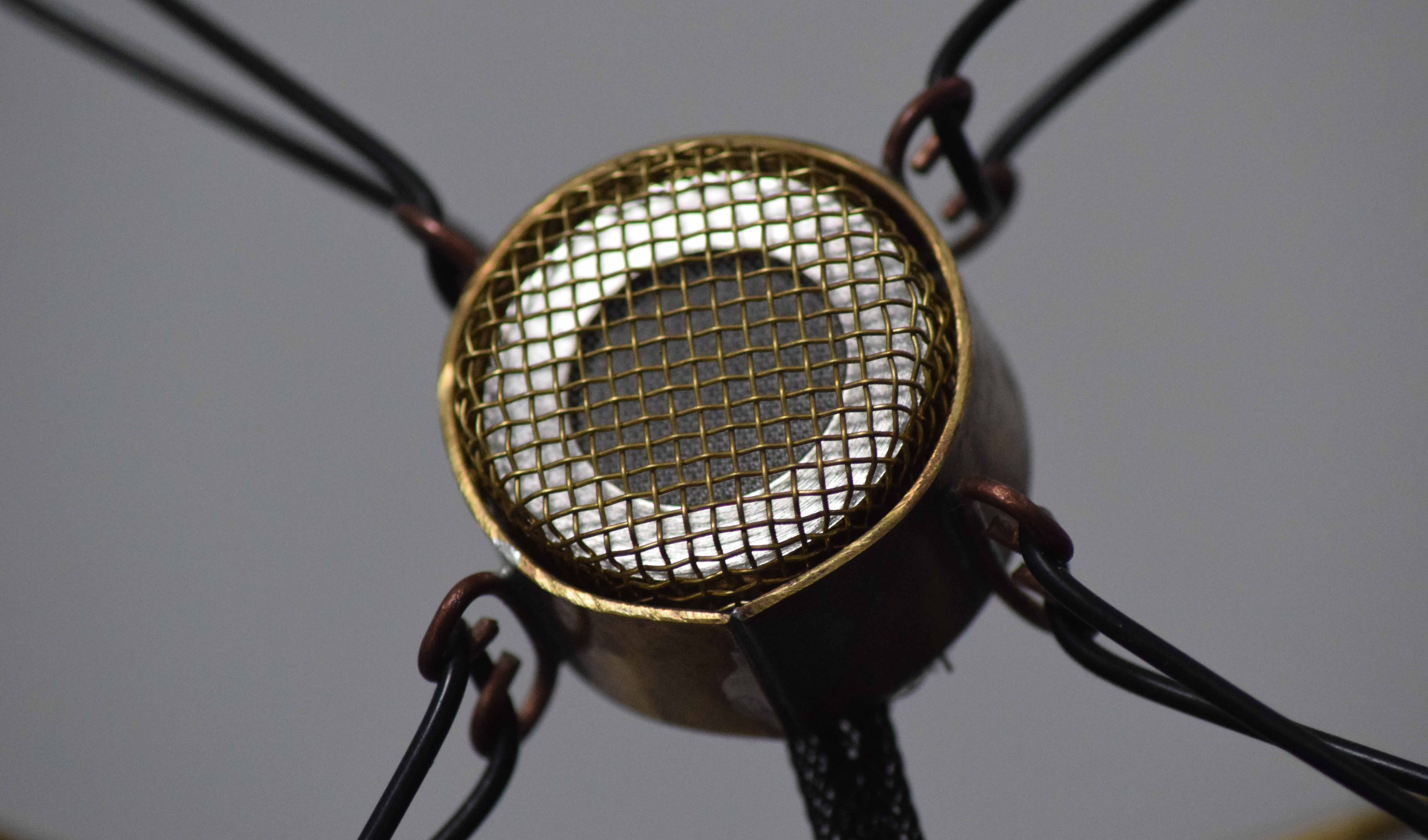
Starting with the 'capsule holder', brass mesh was stamped into a short cylindrical shape using an appropriately sized hole in some wood. Two were required - front and back - with the extraneous corners removed. A hole for the cable was included too. The microphone capsule fits within the mesh, which is then surrounded by a brass ring bent to shape and soldered into a loop. Then, curly C-shaped pieces of copper wire were soldered to the outside of the brass ring. These were used with nitrile O-rings, to suspend the capsule under tension, and act as a shock mount.
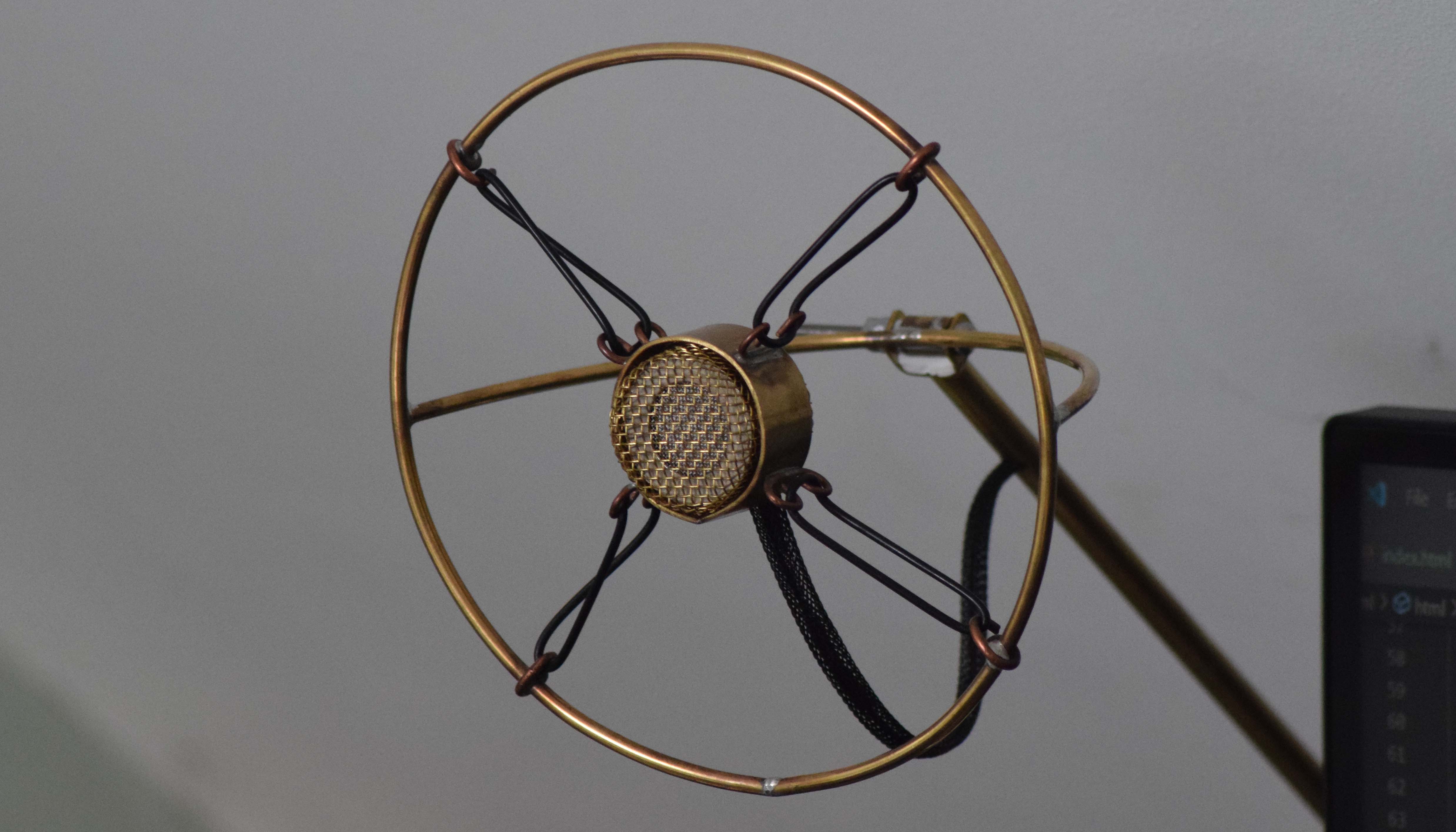
For this, the capsule holder ideally needs to be suspended to four points. I disliked DIY Perks' model for it seems unnecessarily wide and unpractical, so I decided to make a circle instead. With a 3mm brass rod bent and soldered to shape, the capsule holder could be held by a second set of curly wire pieces. However, to connect this to the arm, the capsule holder's holder needs to be held from behind. So another 3mm rod was bent, but into a semi-circle and attached to the back of the capsule holder's holder.
Arm for Capsule Assembly
Moving on, the arm was made using two components: a solid brass rod and a hollow brass rod, of which the solid rod could fit perfectly within the hollow one. This can be used to reduce the weight of the system and allows for some smart (but awkward) cable management.
Two rods will be used to attach to the base, which transferred to a third rod - basically an upside-down Y shape with three separate rods - to allow for vertical articulation. To produce the joint between these rods, the ends of the hollow tubes had to be capped with the solid brass, such that when a hole can be drilled through. Then the appropriate sides of each rod can be filed flat to increase friction between the rods.
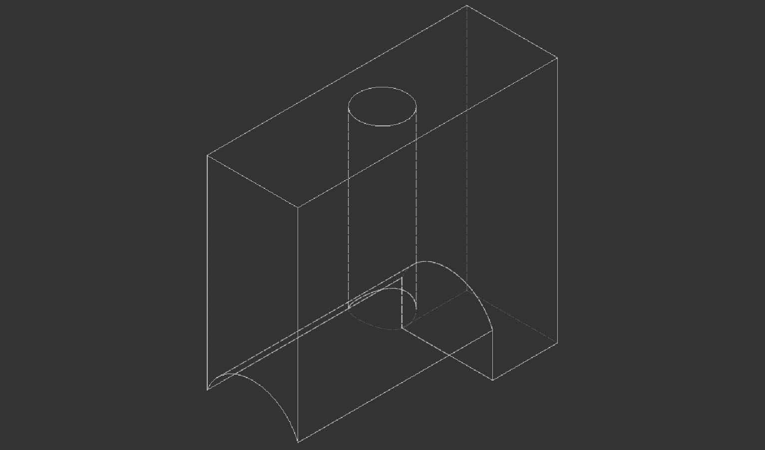
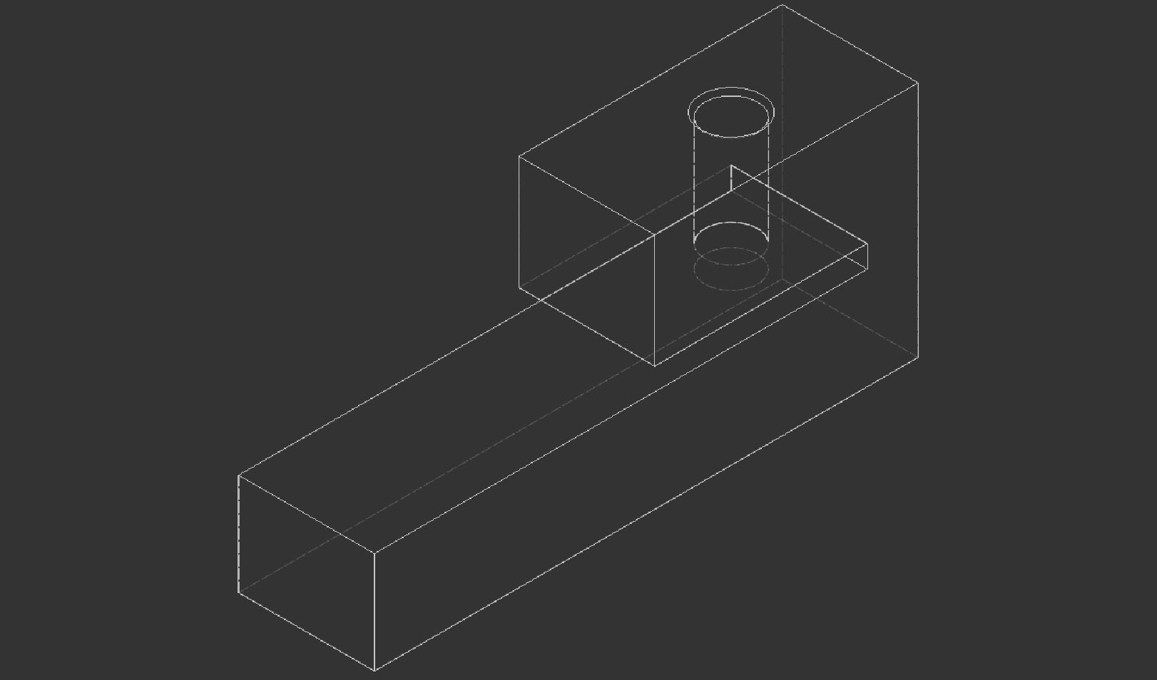
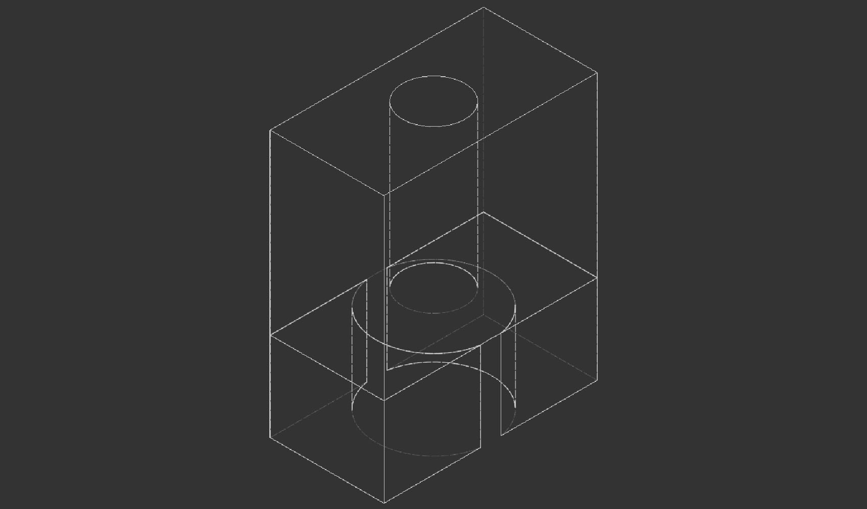
However each rod requires a hole that is an equal distance from its end. The only way to achieve this was with the help of a 3D-printed guide on the the drill stand. Additionally, with a different sized jig, larger holes could also be drilled into the hollow section of the arm to allow cable passthrough from the holder down to the box. It was difficult to thread the sleeved cable down the rod as there were hard-to-access burrs that would drag on the cable sheath and damage it, so this was only done from the microphone to the arm joint. That is the most important section anyway as the cable can sit between the two rods from the arm joint downwards.
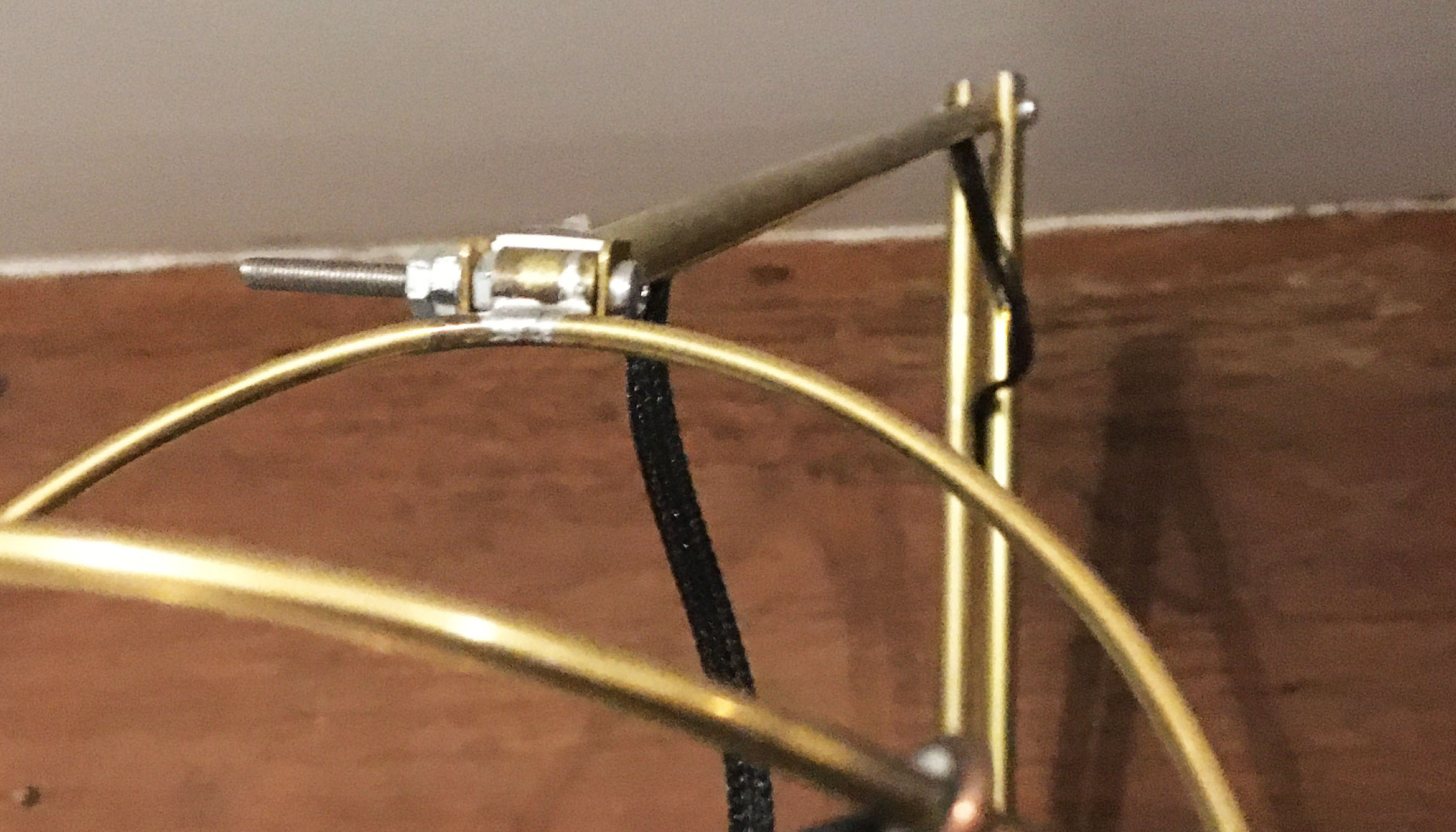
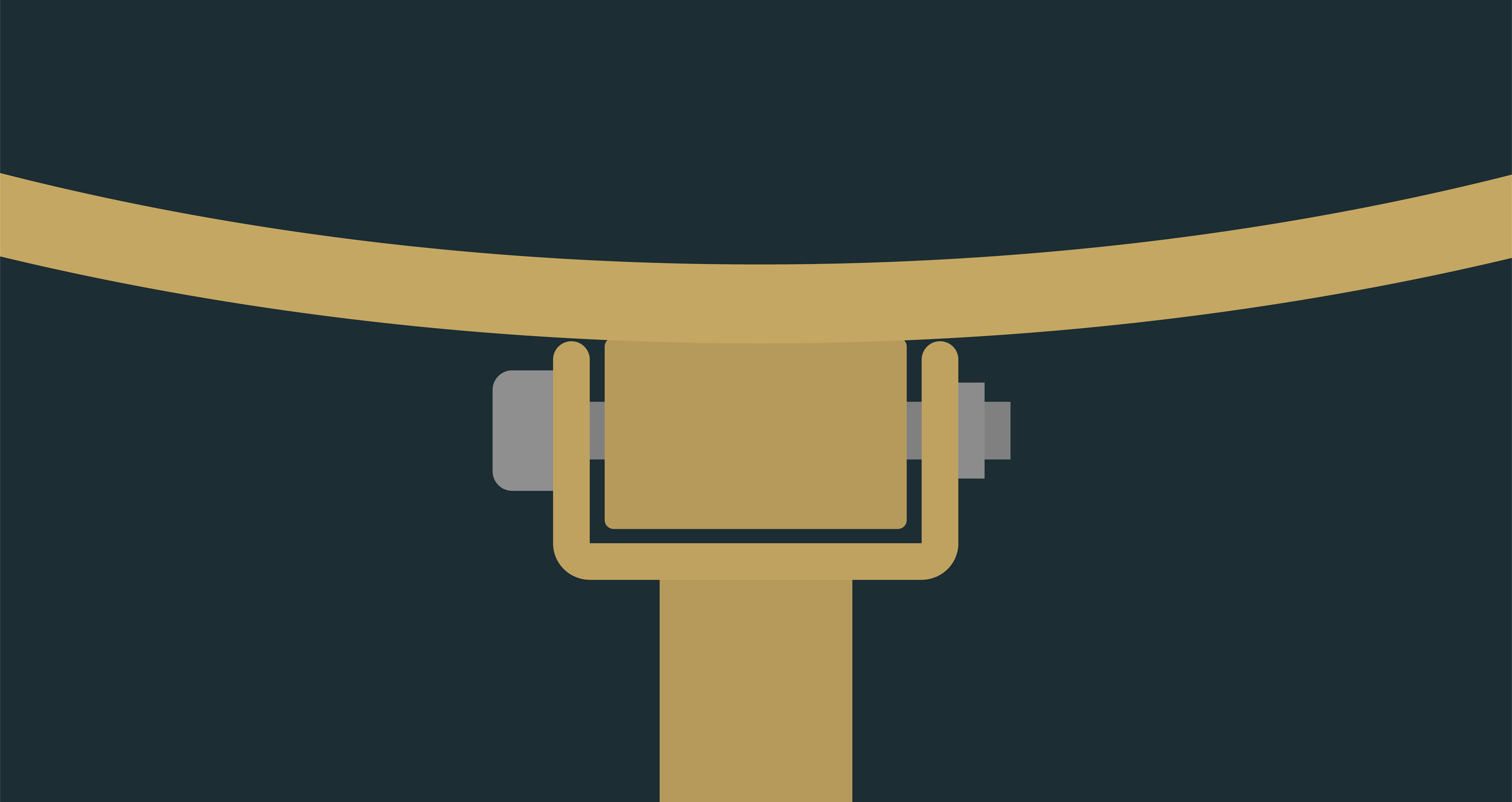
To connect the arm to the capsule assembly and allow the system to articulate, (effectively) a knuckle joint was used to allow vertically movement of the entire capsule assembly. The 'double eye' of the joint was a bent piece of sheet brass (which took a number of attempts to drill accurately and even more to bend accurately). And the 'single eye' is some solid rod with a hole drilled down its length (centrally!). To achieve this was difficult, requiring two more 3D printed guides. For the double eye, the holes had to align centrally on the brass and a specified distance from the end of the flat piece. The single eye just required that it be a straight, central hole all the way through the solid rod.
The double eye then was connected to the end of the single rod from the arm, and the single eye was connected to the semi-circular rod of the capsule holder system.
Ok, great progress so far, but the electronics need to be connected to the microphone, and they need a place to go as well… It's time for the 'electronics box'.
Electronics Box
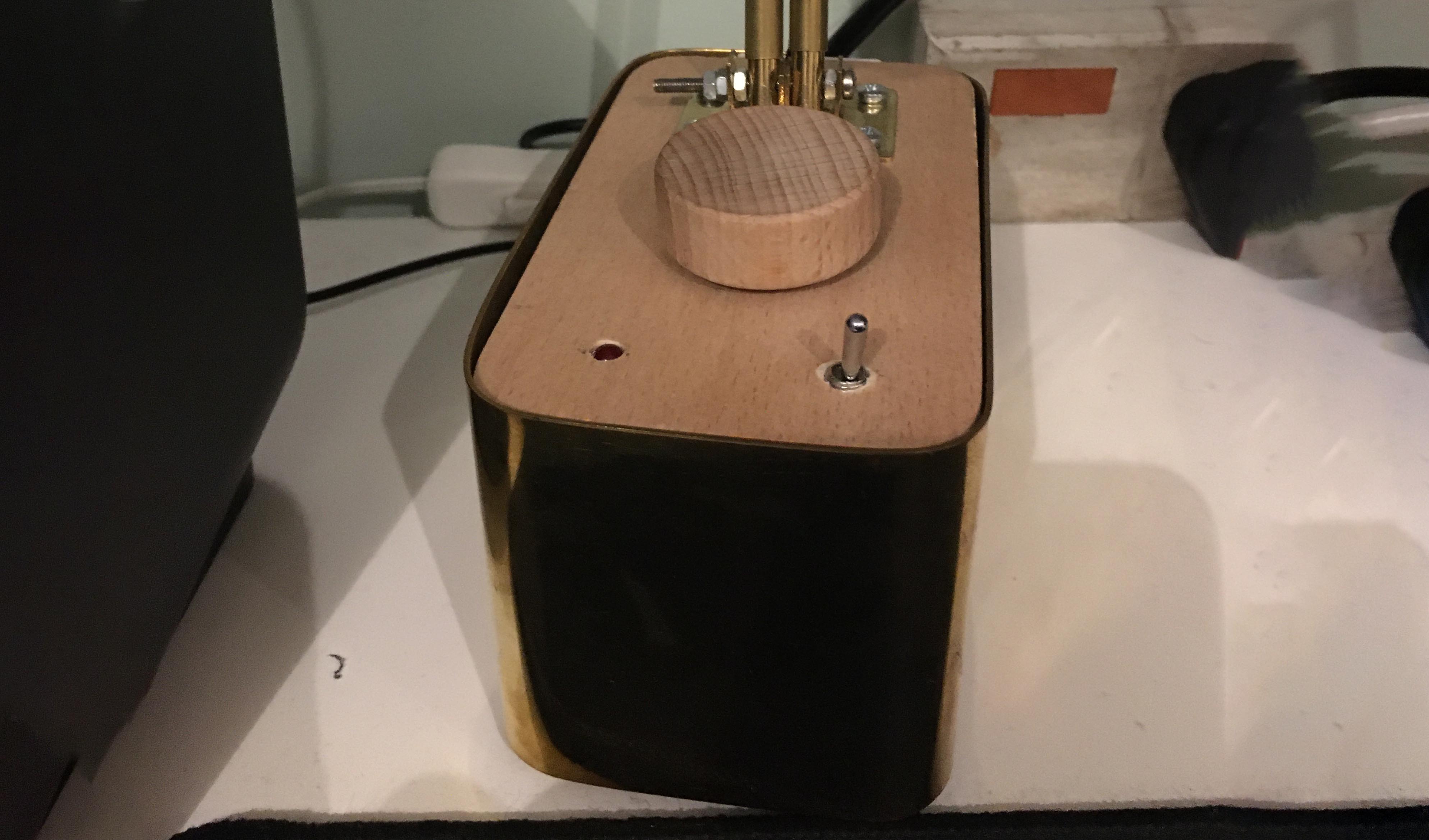
For this, I needed a top plate that could connect to the arm and accommodate the volume knob, power switch and power indicator; a place to add the USB and TRRS ports; and sufficient space for the electronics. Following the aesthetics, brass was to be used predominantly, with the use of wood for the top and bottom plate of the box.
Once this is all put together, this is the final product:
Improvements
There are a number of minor issues with this project, which are caused by a variety of reasons but are mainly due to tolerances of the parts. This is to be expected given the scale and complexity of this design, given my experience. The main issues are as follows:
- The gain of the pre-amp in the electronics box is not high enough as I use the microphone further away from me than I was expecting. Therefore, on maximum volume it's slightly quieter than it should be for normal talking volume.
- The friction created between in the arm joint was not quite as much as desired given the weight of the capsule holding system. This will be due to tolerances and misalignment between the rods' flat surfaces, but ultimately it is not detrimental to the functionality as it still holds its position in certain places - just not all places.
- There are significant issues with the friction in the knuckle joint between the capsule holder and the rod of the arm. I cannot manage to increase the friction of that joint such that the capsule holder does not always sit in its lowest position. This is just an issue with tolerances that I don't think can be fixed without re-making it.
Closing Thoughts
So what have I learnt about brass?
Well its heavy, tarnishes easily, is difficult to work with, but at
least it looks good I guess. I'm pleased with the overall outcome, it
just took (quite) a bit longer that I would have preferred, but that's
mostly my own fault. I suspect that more time was spent figuring out how
to do things, than actually doing them, but this is expected when
dealing with new materials and techniques that have entirely different
requirements to what I've worked with before. Time was spent figuring
out how to make the equipment that I already had behave nicely with the
probably slightly too thick brass sheet, drilling the
appropriate holes in the appropriate pieces within tolerance
and making each part work together.
So whilst it probably lacks the polish that DIY Perks' has, it's just as functional. Although, the brass could probably do with a polish… (ノ ゚ー゚) ノ