Helix and 20-key Macropad Mechanical Keyboards
Introduction
As mechanical keyboards have re-gained in popularity, they has been an ever-increasing number of different customisations and innovations brought to market. Some offer "the fastest" wireless connectivity or include fancy foam for the most precise acoustics, others have LED bars, dials or even screens. There is a spectrum of features, colours and designs - but why find one that suits you when you can design and make your own following your own specification?
So that is what I did.
The premise started with wanted a keyboard that was ergonomic for use at a desk and was more space efficient, without changing layout to the likes of DVORAK. After some research, this resulted in finding split ortholinear layouts, of which the "Helix" was chosen. This consists of 64 keys split between two halves, where each half has its own microcontroller and OLED screen. There is a TRRS jack to connect the two halves (not hot-pluggable), and either microcontroller can be used as the 'master'. Ergonomically, each half can be angled differently such that each hand gets a desirable stagger of keys, and the two halves can be spaced at shoulder-width to avoid straining your wrists. Furthermore, without a dedicated F-row, navigation cluster or numpad, it can be made significantly smaller without compromising on functionality (they can be added back with layers).
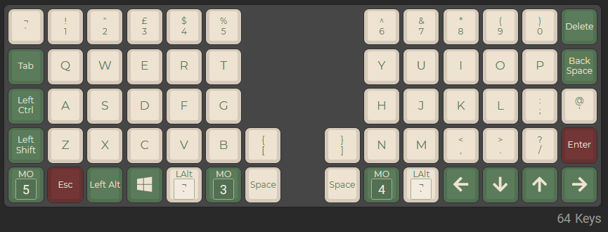
Coming from a standard 100% layout, there was also a desire for a macropad, as certain things like media controls, extended FN keys or applications controls are not on every keyboard - and even if they were, they were never particularly convenient or space efficient. As I was already going to make a Helix, I may as well make a macropad too, right? Well I did, and it works great, the only thing is that once you built a proper mechanical keyboard with layers (in this case five layer keys), you can find plenty of space for all of those extra key bindings. Therefore, unless I need a full, not-on-a-layer numpad, the macropad has provided little purpose and sits in a box under my desk... But as I went to the effort of making it, I may as well show it off here too (ノ ゚ー゚) ノ.
Lets get down to business, how was it done?
Designing the case
Macropad Prototype
Instead of attempting to hand-wire my first mechanical keyboard, I decided to get some PCBs - Helix are available under an MIT license and my brother designed the macropad's - the files just needed sending off to be made.
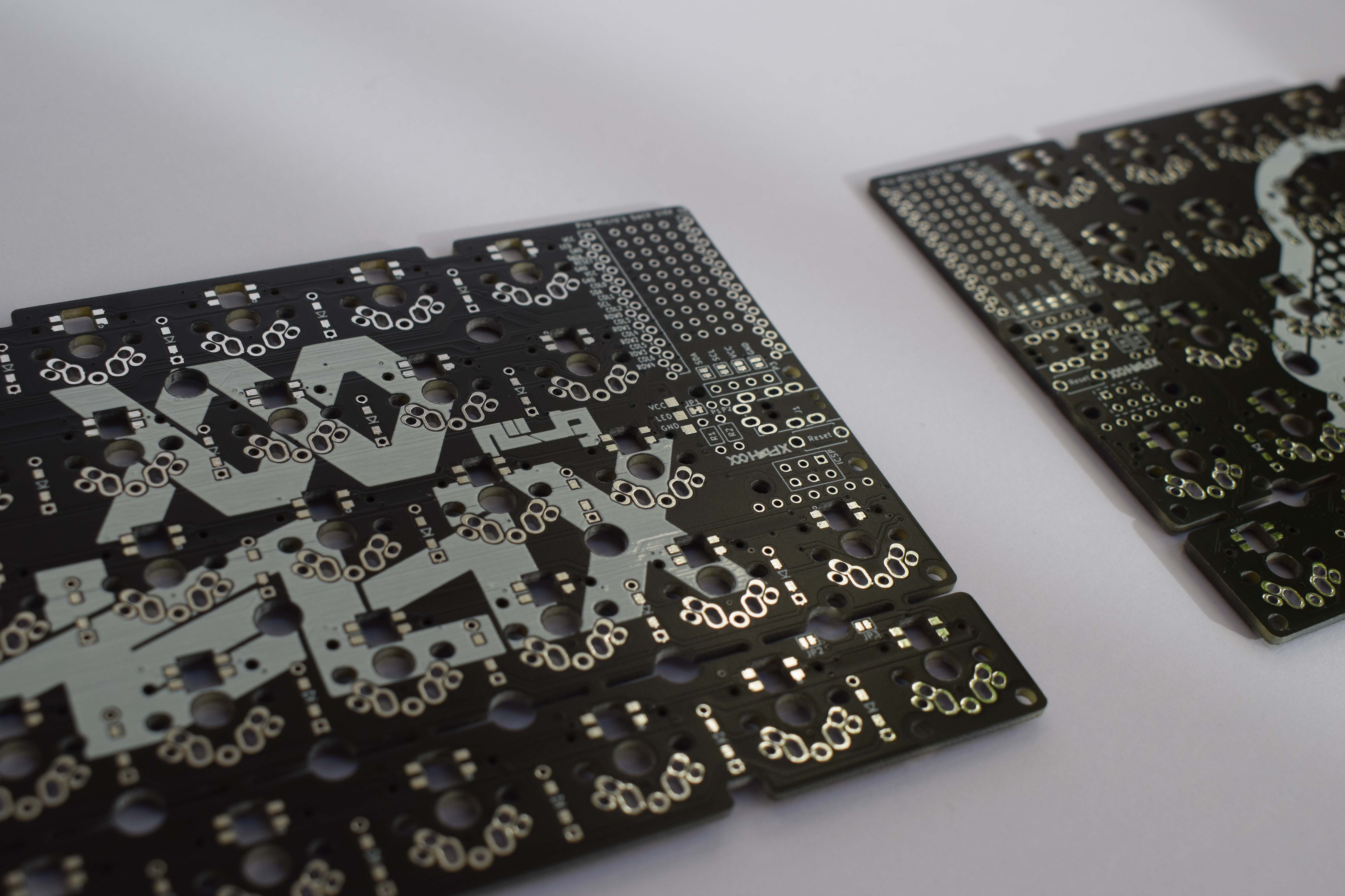
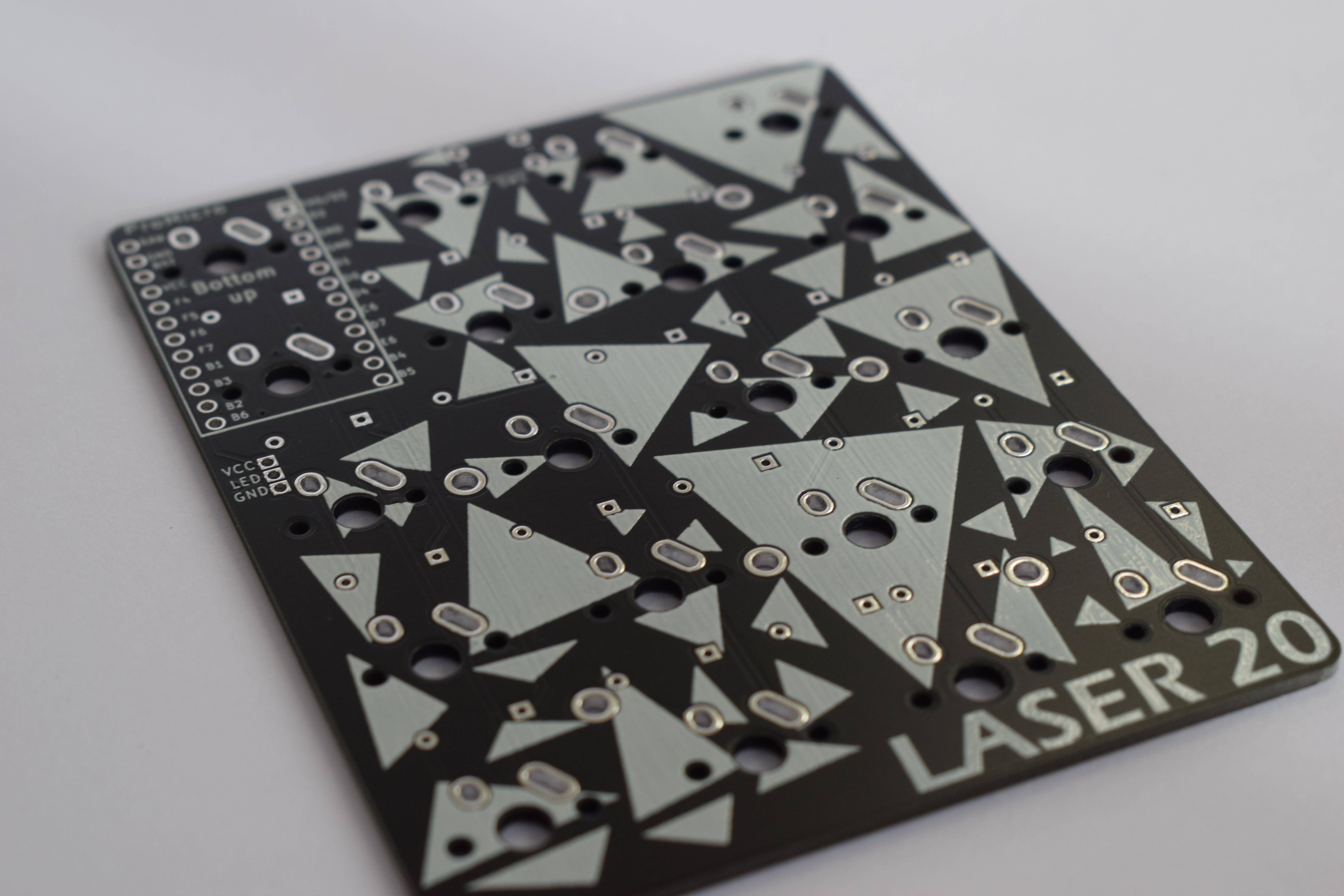
Obviously we need switches and keycaps too, some appropriate cables, and the aforementioned microcontrollers, OLED screens and connectors. Ok, what's left? Oh wait I still need to design the case...
Material choice, whilst important, was fairly limited - I didn't have a 3D printer (yet), I couldn't really do anything with metal and I certainly didn't have the woodworking skills to do anything by hand, so instead I managed to acquire temporary access to a nearby laser cutter. But how can you build a case with laser cut pieces? There are many existing case mounting designs, and if you're interested in looking in to them, here is a brilliant diagram by Thomas Baart, but as I'm using a laser cutter, I need to get a bit more creative.
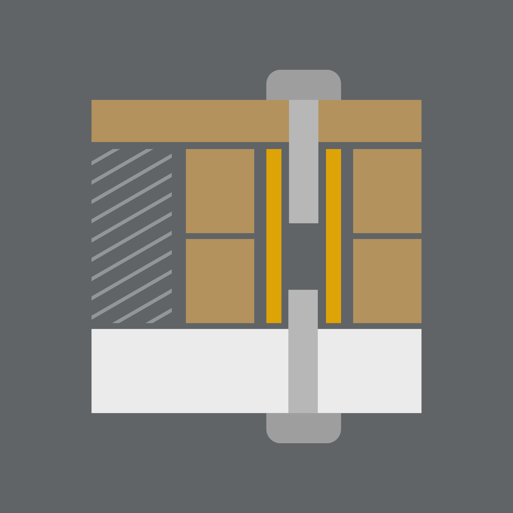
The case was
to be made of layers of material of appropriate thickness for their purpose. To fasten
the layers
together, a 'female to female' standoff was placed in the internal layers with M2 screws at either
end, through
the top and bottom plates. Give it some rubber feet and this works surprisingly well. 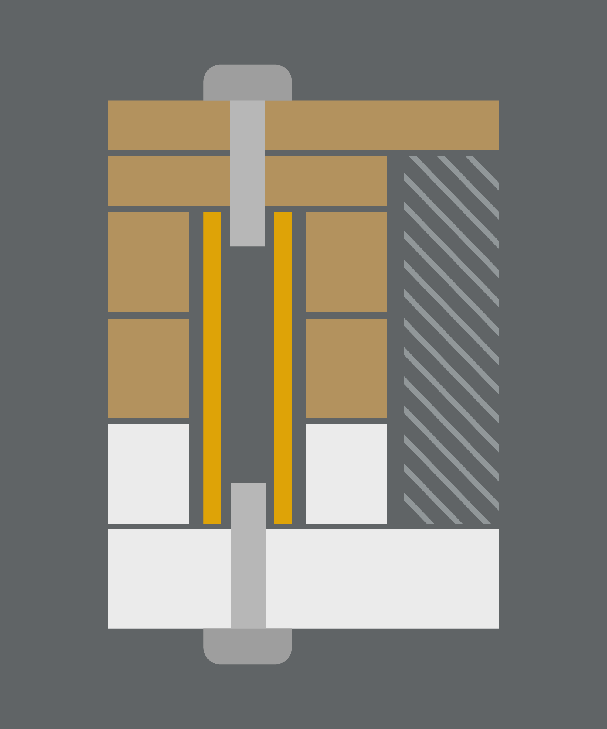 Macropad
Case StructureThe starting
point of
design was with the switches - for simplicity, it was designed to be plate mount, with the plate, in
this case,
being 1.5mm plywood. This thickness was required as that is the standard at which switches clip
into. Then I
needed to calculate the minimum internal space required.
It was decided that the helix required two 3mm layers for the internals and three 3mm layers would
be
sufficient
for the macropad, then an extra layer for the base below that. The macropad would need slightly more
space due
to the microcontroller being placed on the underside of the PCB. This meant that the macropad case
didn't need
to be made larger to accommodate it around the side of the keys - unlike the helix which already has
a section
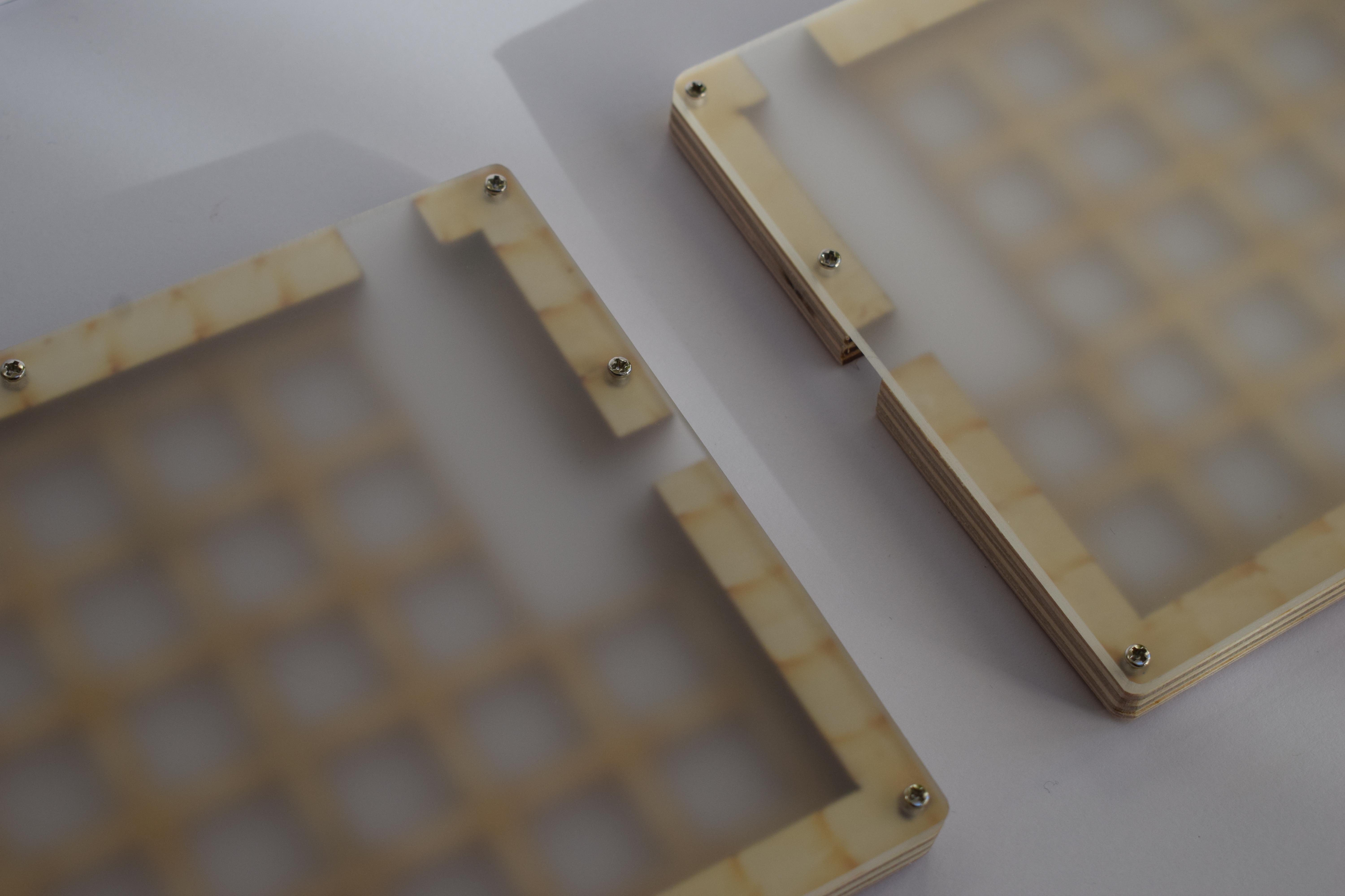
for it. For something more interesting, frosted acrylic was chosen for the bottom layer. This choice
of material
and thickness produces a very strong shell which is very rigid whilst remaining surprisingly light.
All in all,
13.5mm of case is fairly reasonable, and everything just about fit; for the helix anyway...
After ordering the required materials, I began to test and prototype, starting with the macropad as it was smaller and less material would be used in any failed designs.
For material efficiency, the inner layers started out as tapered rectangles - one for each side of the case - that would sit together and be secured as a whole. However, with the tolerances of the laser cutter (it had some issues that were only properly noted and rectified at a later point) there were concerns of the alignment between layers. Even when fully constructed, there was possibility of the individual pieces moving due to the dimensions of the screw holes. This meant that a complete rectangle would be most appropriate for a sturdy design.
And the first prototype was complete:
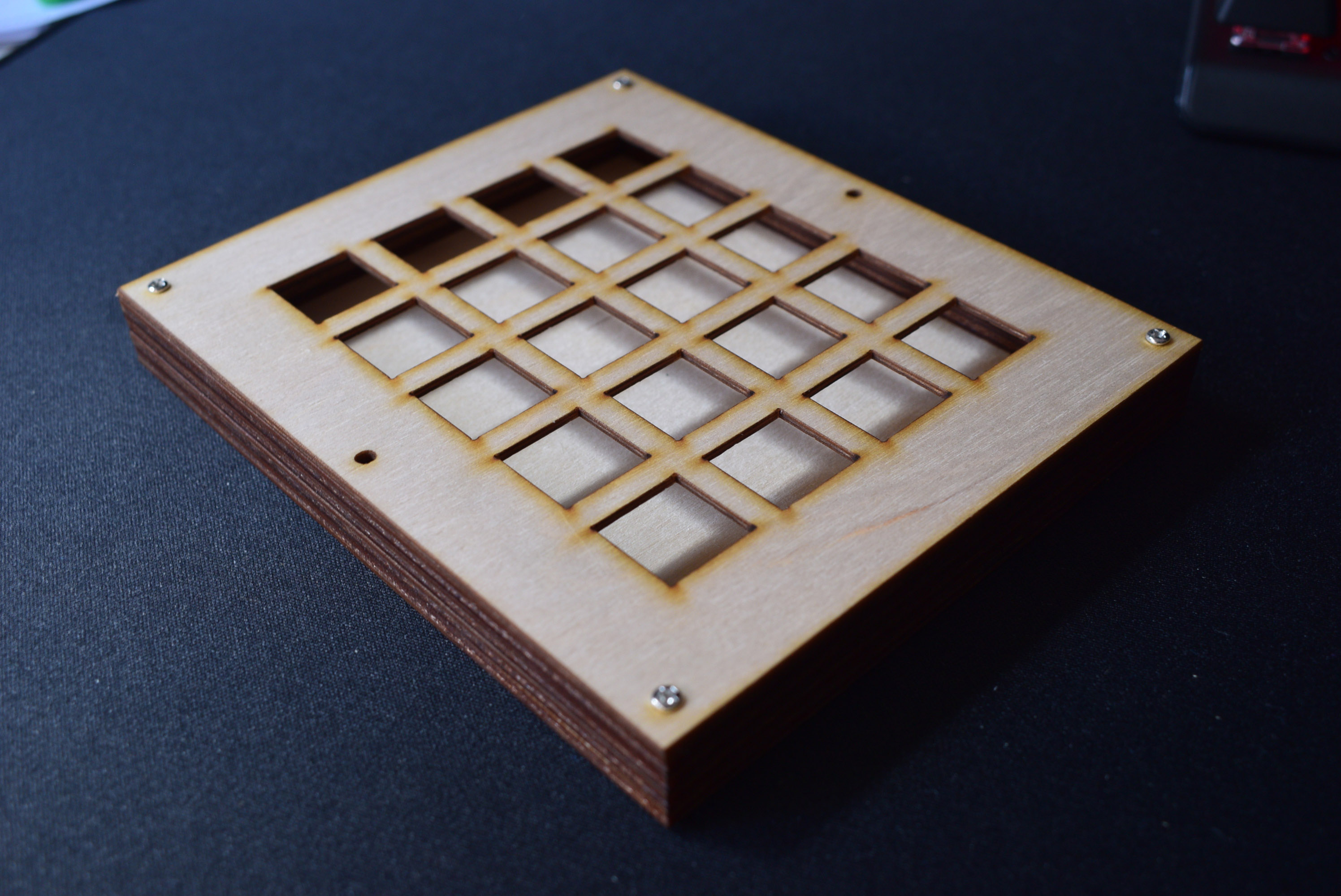
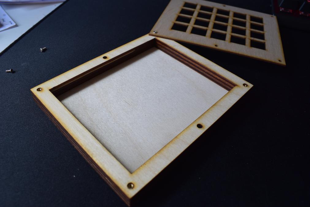
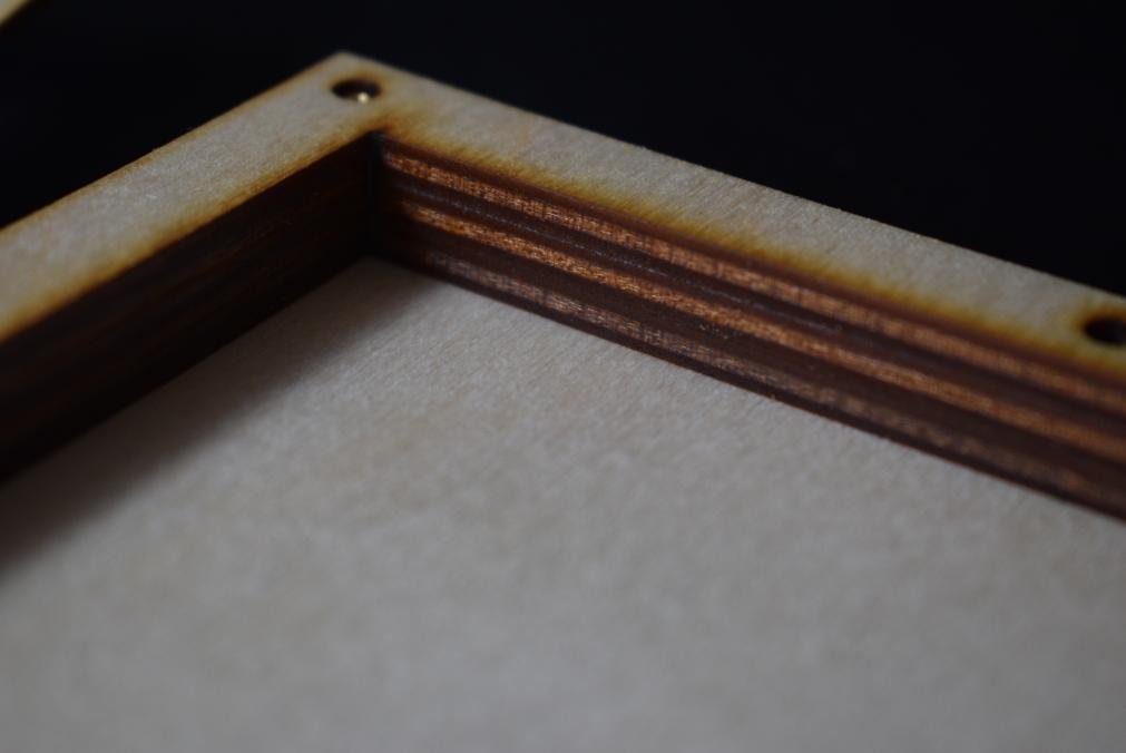
This overall was a success, with only some minor tweaks, namely reducing the size of the borders. After the case was constructed, it was put on the belt sander to remove the burnt wood edges, and once the laser cutter was fixed, the acrylic could also be cut for the bottom layer. Once the first 'production' model was made, I put together the electronics for the macropad, and noticed one slight fitment issue. There was not quite enough internal space, so with some leftover 1.5mm plywood, I had to use the tapered rectangle design for a booster layer just below the top plate.
Helix Prototype
 Helix
Case StructureNow that the concept was brought to reality, I just needed to do
the same for the Helix, which is
larger and more
complicated. As like last time, I took measurements, produced the CAD and cut the materials, but
made the
foolish mistake of assuming that the two halves were symmetrical - they were not as the TRRS jack is
slightly
offset between them as the PCB was reversible (one PCB layout for both halves). Once that was
sorted, the rest
of the pieces could be cut.
Side note - the complete rectangle shape that was used for the middle layers was such that the macropad layers could be nested within the Helix layers to reduce waste.
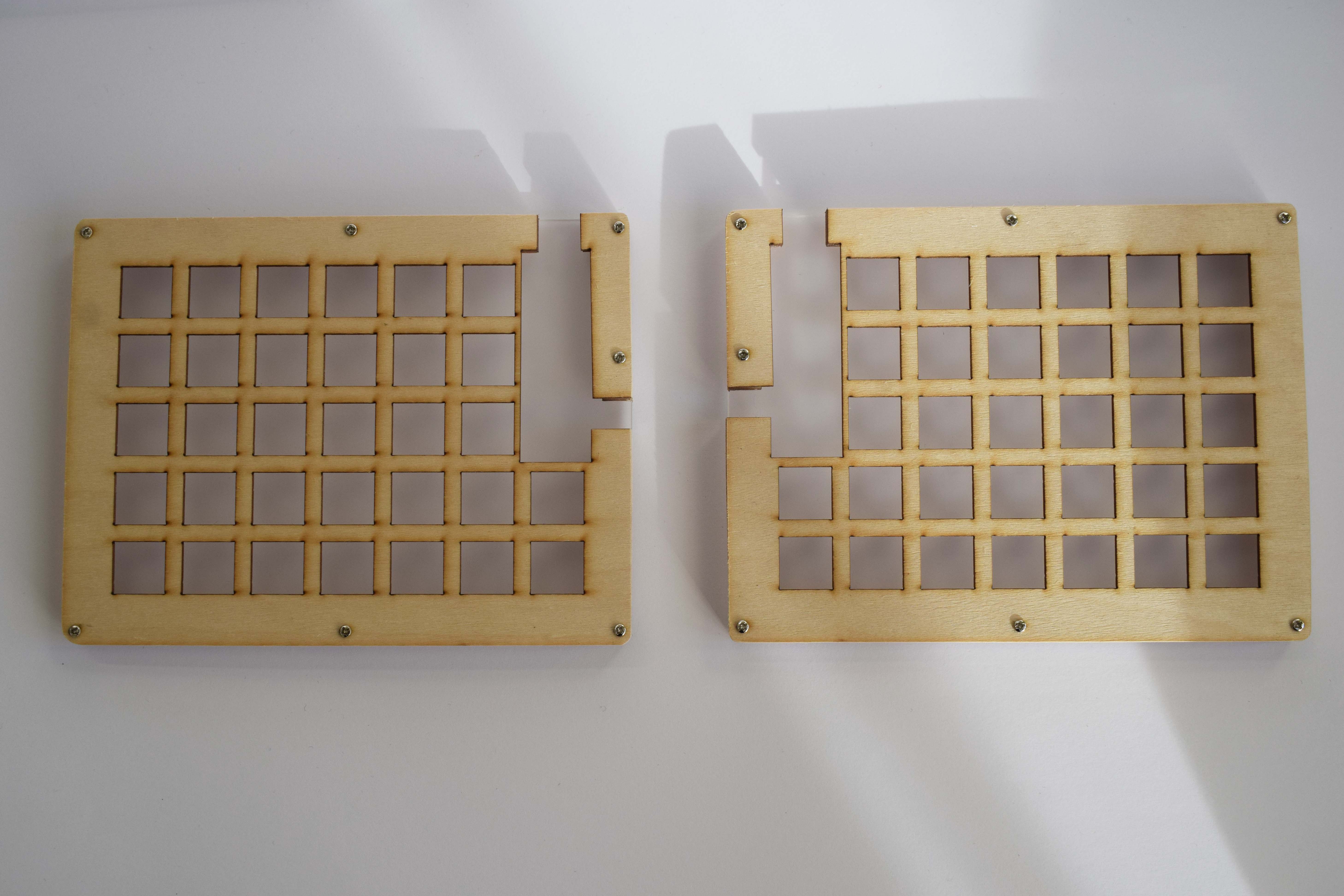
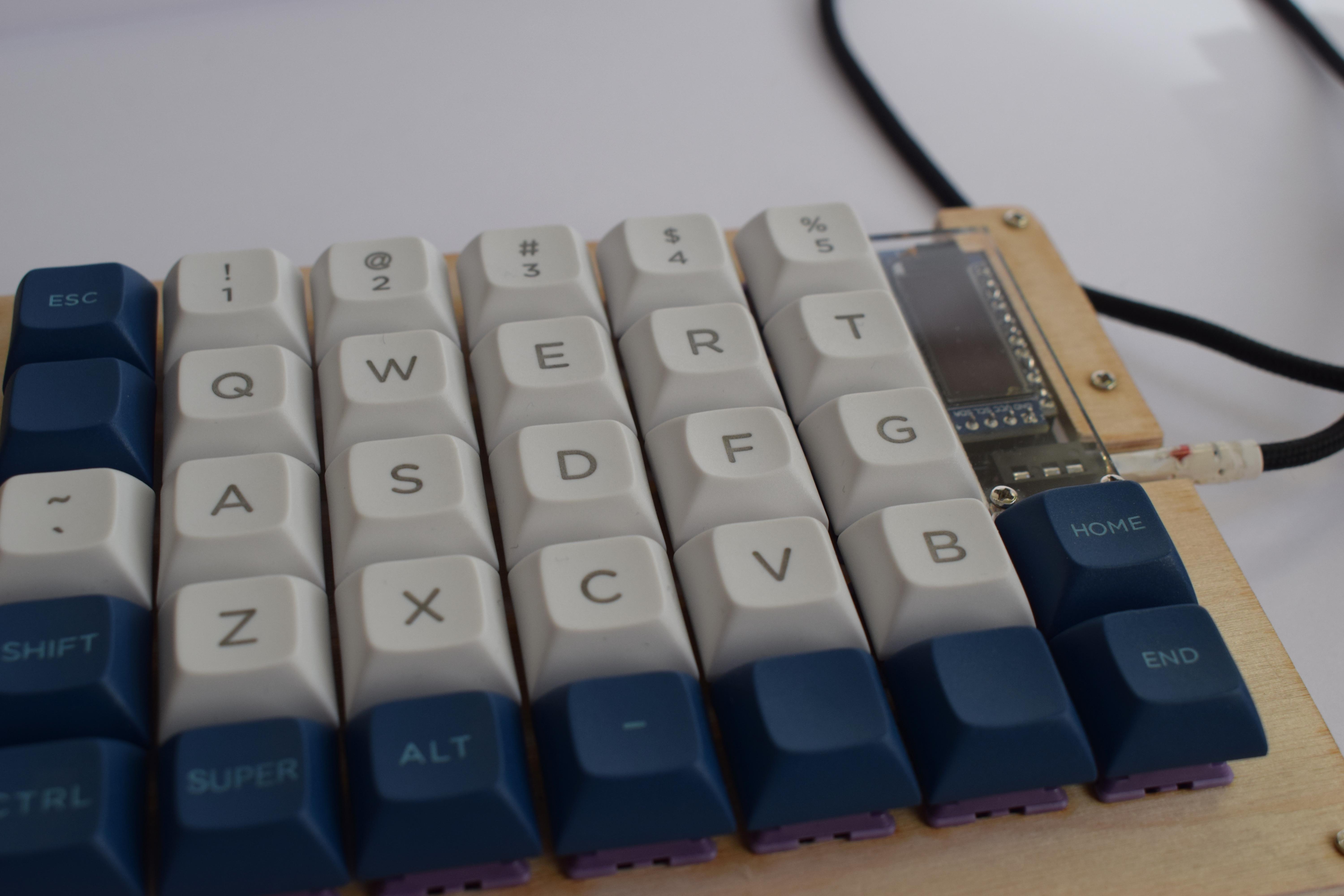
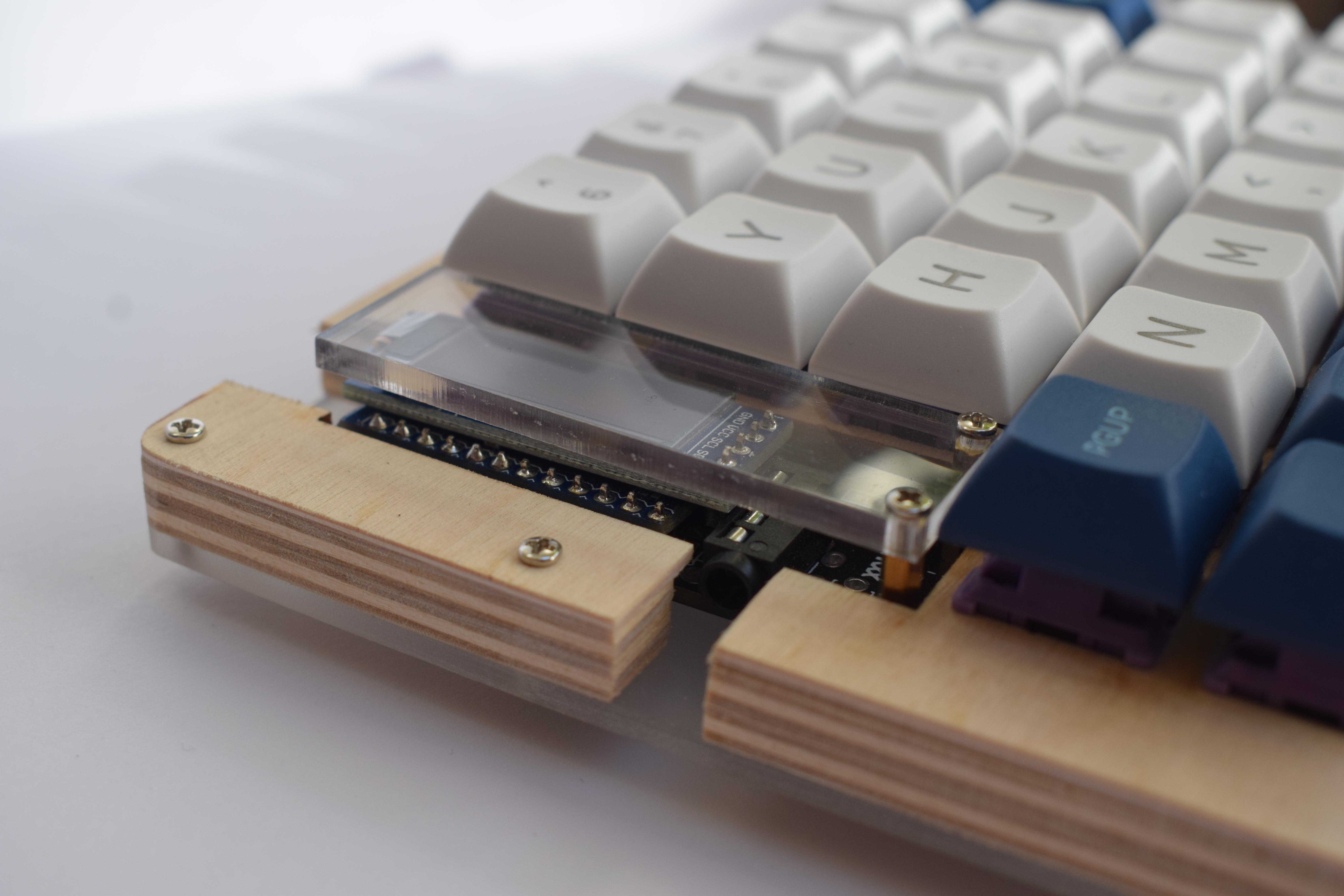
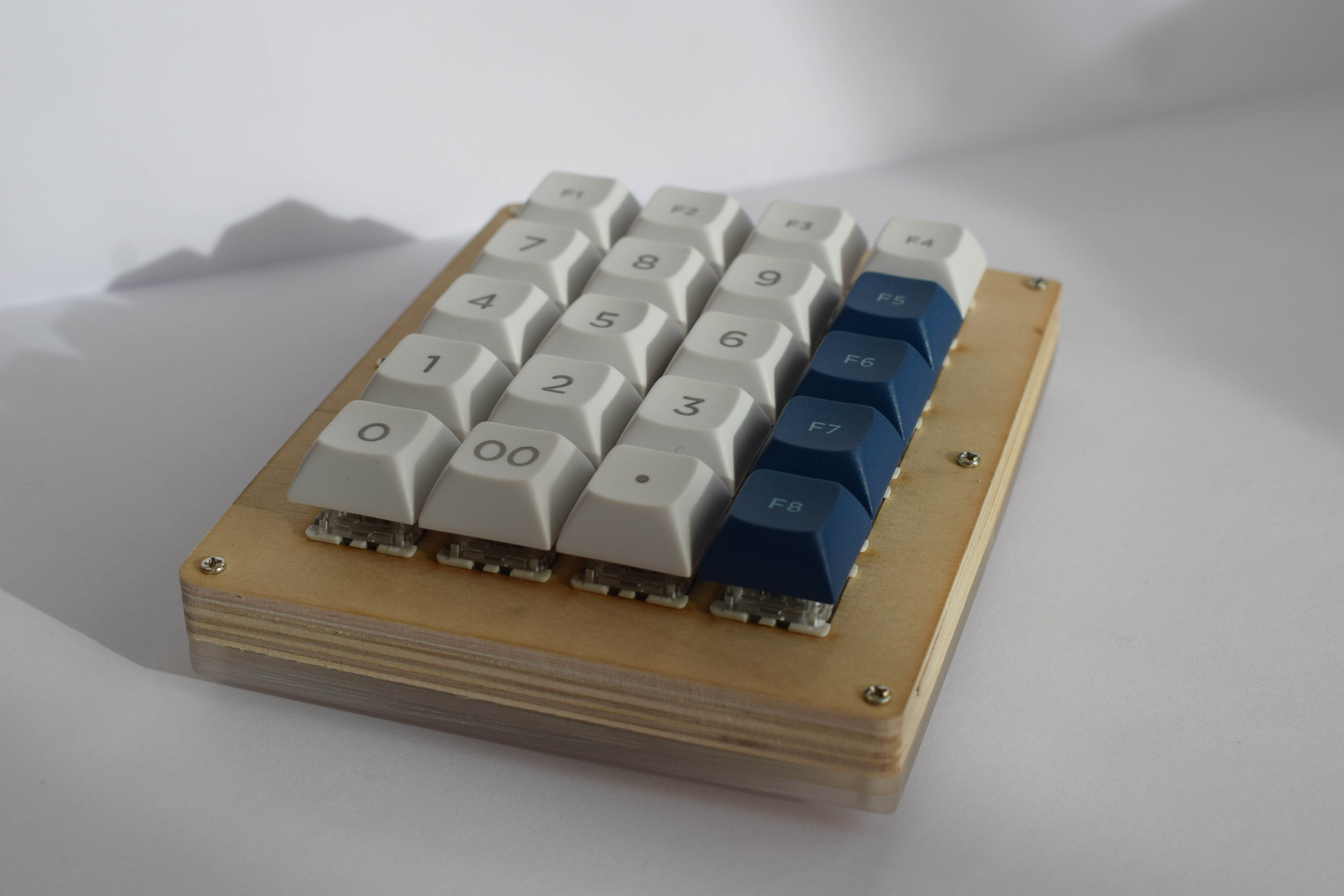
Once everything was soldered, firmware was loaded, and the keycaps added, the project was complete. Here's a showcase of the final results:
Updates:
Don't use Pro Micro microcontrollers with USB Micro-B connectors as they are incredibly fragile, and a pain to replace at a later date. If you do, use Mill-Max connectors for 'hot-swap' capabilities.
Also don't mix ports of microcontrollers - e.g. a Micro-B and a Type-C variant - as the boards don't always play nicely with each other. This may also lead to needing to replace them after the fact...